Posts Tagged ‘drain’
Monday, October 14th, 2013
|
We’ve been discussing various aspects of a power plant’s water-to-steam cycle, from machinery specifics to identifying inefficiencies, and today we’ll do more of the same by introducing the condenser hot well and discussing its importance as a key contributor to the conservation of energy, specifically heat energy. Let’s start by returning our attention to the steam inside the condenser vessel.
Last week we traced the path of the condenser’s tubes and learned that the cool water contained within them serve to regulate the steam’s temperature surrounding them so that temperatures don’t rise dangerously high. To fully understand the important result of this dynamic we have to revisit the concept of latent heat energy explored in a previous article. More specifically, how this energy factors into the transformation of water into steam and vice versa.
Steam entering the condenser from the steam turbine contains latent heat energy that was added earlier in the water/steam cycle by the boiler. This steam enters the condenser just above the boiling point of water, and it will give up all of its latent heat energy due to its attraction to the cool water inside the condenser tubes. This initiates the process of condensation, and water droplets form on the exterior surfaces of the tubes.
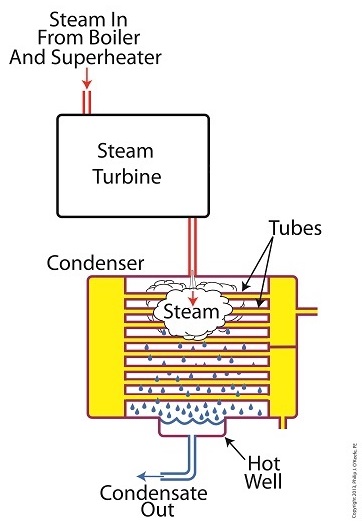
The water droplets fall like rain from the tube surfaces into the hot well situated at the bottom of the condenser. This hot well is essentially a large basin that serves as a collection point for the condensed water, otherwise known as condensate.
It’s important to collect the condensate in the hot well and not just empty it back into the lake, because condensate is water that has already undergone the process of purification. It’s been made to pass through a water treatment plant prior to being put to use in the boiler, and that purified water took both time and energy to create. The purified condensate also contains a lot of sensible heat energy which was added by the boiler to raise the water temperature to boiling point, as we learned in another previous article. This heat energy was produced by the burning of expensive fuels, such as coal, oil, or natural gas.
So it’s clear that the condensate collecting in the hot well has already had a lot of energy put into it, energy we don’t want to lose, and that’s why its an integral part of the water-to-steam setup. It acts as a reservoir, and the drain in its bottom allows the condensate to flow from the condenser, then follow a path to the boiler, where it will be recycled and put to renewed use within the power plant.
Next week we’ll follow that path to see how the condensate’s residual heat energy is put to good use.
________________________________________ |
Tags: boiler, boiling point, coal, coal fired boiler, condensate, condensed water, condenser, drain, electric utility power plant, engineering expert witness, forensic engineer, fuel, heat energy, hot well, latent heat energy, licensed professional engineer, machinery, mechanical engineer, natural gas, oil, power engineer, power plant engineer, power plant training seminars, purified water, residual heat energy, sensible heat energy, steam turbine, water droplets, water temperature, water treatment plant, water-to-steam cycle
Posted in Engineering and Science, Expert Witness, Forensic Engineering, Innovation and Intellectual Property, Personal Injury, power plant training, Product Liability | Comments Off on How A Power Plant Condenser Works, Part 3
Monday, July 9th, 2012
| The Olympic Torch relay, soon to culminate in London, is the grand daddy of all relays, starting in one country, traversing many others, then ending its journey at the site of the Olympic Games. It passes through many athletes’ hands while on its journey, its final purpose being to light the Olympic Flame. Less glamorous, though still useful, is the relay race that often takes place within digital controls.
Last time we looked at my design solution for the control of a microprocessor controlled medical x-ray film developing machine, where a field effect transistor (FET) acted as a digital control interface between a 5 volt direct current (VDC) microprocessor and a 12 VDC buzzer. Well, controlling the buzzer wasn’t the only function of the microprocessor. It also had to control a 120 volt alternating current (VAC) drive motor, the purpose of which was to move x-ray film through a series of processes within the machine. Yet another requirement was that the machine’s drive motor run 40 minutes upon activation by a start button, then shut off.
One of the challenges presented by this specification was that an FET standing alone is only suited to control direct current devices like the buzzer, but not alternating current devices like electric motors. Direct current flows in one direction only when traveling through wire, and since an FET can only pass current in one direction it is the perfect match for those applications.
Now, as the name would imply, alternating current flow alternates, that is, it reverses direction and varies in intensity many times each second. This is a scenario that FETs are not equipped to handle because they can’t deal with reverse flow. This meant that, for the purpose of my developing machine, I could not use an FET to directly control the 120 VAC motor. Now let’s take a look at Figure 1 to get a basic look at how I solved the problem.
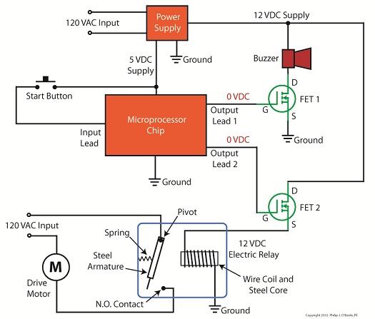
Figure 1
Figure 1 shows not one, but two green FET’s, each branching off from the microprocessor chip. We’ll call them FET 1 and FET 2. If you recall from last time, the buzzer works on 12 VDC, so FET 1 works well as a direct interface between it and the microprocessor chip. But in the case of FET 2 we need an intermediary device to handle the alternating current motor. That device is a 12 VDC electric relay.
In an earlier blog series on industrial controls I discussed how electric relays use electromagnets to power light bulbs and motors on and off in response to someone pressing a button on a control panel. We have very much the same mechanics at play in our developing machine. The relay will power the motor on and off in response to the computer program running within the 5 VDC microprocessor, a programming sequence that is initiated by someone pressing a button.
To get the motor control to work in the machine, the gate (G) of FET 2 is connected to another output lead on the microprocessor. We’ll call that Output Lead 2. Then, the source (S) of FET 2 is connected to the wire coil in the relay. To tap into the power source for the relay, the drain (D) of FET 2 is connected to the 12 VDC supply. Finally, the other end of the relay coil is connected to electrical ground.
Next time we’ll activate the pushbutton and see how the control initiative passes along a path in a manner reminiscent of the flame in an Olympic Torch relay, but here it passes between the microprocessor, the FET and electrical relay, culminating in power to the drive motor.
____________________________________________ |
Tags: 12 VDC, 120 VAC, alternating current, digital control, digital control interface, digital input, digital output, direct current, drain, drive motor, electric current, electric motor control, electric motors, electric relay, electrical ground, electronic device, engineering expert witness, FET, field effect transistor, forensic engineer, gate, machine control, microprocessor, microprocessor chip, output lead, pushbutton, relay coil, source, start button, transistor, x-ray film machine
Posted in Engineering and Science, Expert Witness, Forensic Engineering, Innovation and Intellectual Property, Personal Injury, Product Liability | 1 Comment »
Sunday, June 24th, 2012
| Not too long ago I was retained as an engineering expert to testify on behalf of a plaintiff who owned a sports bar. The place was filled with flat screen televisions that were plugged into 120 volt alternating current (VAC) wall outlets. To make a long story short, the electric utility wires that fed power to the bar were hit by a passing vehicle, causing the voltage in the outlets to increase well beyond what the electronics in the televisions could handle. The delicate electronics were not suited to be connected with the high voltage that suddenly surged through them as a result of the hit, and they overloaded and failed.
Similarly, lower voltage microprocessor and digital logic chips are also not suited to directly connect with higher voltage devices like motors, electrical relays, and light bulbs. An interface between the two is needed to keep the delicate electronic circuits in the chips from overloading and failing like the ill fated televisions in my client’s sports bar. Let’s look now at how a field effect transistor (FET) acts as the interface between low and high voltages when put into operation within an industrial product.
I was once asked to design an industrial product, a machine which developed medical x-ray films, utilizing a microprocessor chip to automate its operation. The design requirements stated that the product be powered by a 120 VAC, such as that available through the nearest wall outlet. In terms of functionality, upon startup the microprocessor chip was to be programmed to first perform a 40-minute warmup of the machine, then activate a 12 volt direct current (VDC) buzzer for two seconds, signaling that it was ready for use. This sequence was to be initiated by a human operator depressing an activation button.
The problem presented by this scenario was that the microprocessor chip manufacturer designed it to operate on a mere 5 VDC. In additional, it was equipped with a digital output lead that was limited in functionality to either “on” or “off” and capable of only supplying either extreme of 0 VDC or 5 VDC, not the 12 VDC required by the buzzer.
Figure 1 illustrates my solution to this voltage problem, although the diagram shown presents a highly simplified version of the end solution.
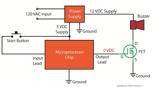
Figure 1
The illustration shows the initial power supplied at the upper left to be 120 VAC. This then is converted down to 5 VDC and 12 VDC respectively by a power supply circuit. The 5 VDC powers the microprocessor chip and the 12 VDC powers the buzzer. The conversion from high 120 VAC voltage to low 5 and 12 VDC voltage is accomplished through the use of a transformer, a diode bridge, and special transistors that regulate voltage. Since this article is about FETs, we’ll discuss transistor power supplies in more depth in a future article.
To make things a little easier to follow, the diagram in Figure 1 shows the microprocessor chip with only one input lead and one output lead. In actuality a microprocessor chip can have dozens of input and output leads, as was the case in my solution. The input leads collect information from sensors, switches, and other electrical components for processing and decision making by the computer program contained within the chip. Output leads then send out commands in the form of digital signals that are either 0 VDC or 5 VDC. In other words, off or on. The net result is that these signals are turned off or on by the program’s decision making process.
Figure 1 shows the input lead is connected to a pushbutton activated by a human. The output lead is connected to the gate (G) of the FET. The FET is shown in symbolic form in green. The FET drain (D) lead is connected to the buzzer and its source (S) lead terminates in connection to electrical ground to complete the electrical circuit. Remember, electric current naturally likes to flow from the supply source to electrical ground within circuits, and our scenario is no exception.
Next time we’ll see what happens when someone presses the button to put everything into action.
____________________________________________
|
Tags: 12 VDC, 120VAC, 5 VDC, alternating current, digital control, digital control interface, digital interface, digital logic chips, diode bridge, direct current, drain, electric ground, electric relays, electric utility, electrical circuit, electronic devices, engineering expert witness, FET, field effect transistor, forensic engineer, gate, high voltage, industrial product, input signal, light bulbs, low voltage, microprocessor control, motors, output signal, overloaded, power supply, pushbutton, source, surge, television, transformer, transistors, voltage regulator, x-ray film machine
Posted in Engineering and Science, Expert Witness, Forensic Engineering, Innovation and Intellectual Property, Personal Injury, Product Liability, Professional Malpractice | Comments Off on Transistors – Digital Control Interface, Part II
Sunday, June 10th, 2012
| Back in the 60s my dad spent about $25 to buy a small transistor radio. That was a lot of money in those days, but well worth it. The new transistor technology allowed for a much less cumbersome radio to be produced. No more lugging around big radios armed with heavy vacuum tubes. In the years that followed the word transistor became a household word. They were employed in a variety of ways within televisions and other electronic devices, increasing both their reliability and functionality.
So what is a transistor and what does it do? It’s an electronic component, developed in the late 1940s. The first transistor was about as big as a softball and crudely made. As such, it was too impractical for commercial use. Then in the l950s technological advancements made commercial production of smaller, high-quality transistors possible. Transistors enjoyed widespread introduction to the consuming mainstream in the l960s, and since then they’ve been made in many different types, shapes, and sizes. Some are shown in Figure 1 below.
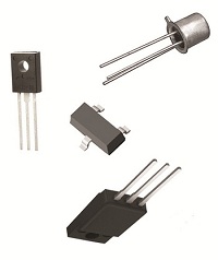
Figure 1
A commonly used type of transistor is called a field effect transistor, or FET, one of which is shown in Figure 2. The FET has three metal leads which allow it to be connected into electrical circuits. These leads are referred to as the drain (D), the source (S), and the gate (G).

Figure 2
FET’s control the flow of current within an electronic circuit. A good way to understand what they do is to consider the analogy of water flowing through a faucet.
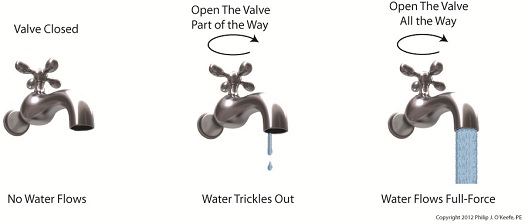
Figure 3
Figure 3 shows a faucet, complete with valve and handle. With the valve closed the flow of water is completely shut off. If the valve is opened partway by rotation of the handle, a trickle of water emerges. The more the handle is turned and valve is opened, the greater the flow of water.
The FET shown in Figure 4 operates a lot like a faucet, but with regard to electrical current.
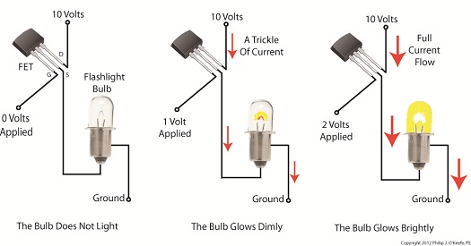
Figure 4
The FET controls the flow of current flowing through its D and S leads, but it does not employ a valve or handle to do it. Rather, flow rate is controlled by application of a small amount of voltage to the G lead. The voltage’s influence on the G lead influences the FET to permit current to flow in through the D lead, then out through the S lead. The amount of voltage applied to the G lead is directly related to how much current will be allowed to flow.
In this example the D lead on the FET is connected to a 10 volt direct current (VDC) power supply. The S lead is connected to a flashlight bulb which is connected to electrical ground. If you will remember from previous blogs, electric current naturally wants to flow from the supply source to ground, much like water wants to naturally flow downhill.
If the bulb was connected directly to the 10 VDC power supply, current would flow through unimpeded and the bulb would light. However, in Figure 4 the FET acts as a regulating device. It’s connected between the 10 VDC power supply and the bulb. When no voltage is applied to the G lead the FET acts like a closed valve and current is unable to flow. Without current we, of course, have no light.
When a low amount of voltage, say one volt, is applied to the G lead, the FET acts like a partially opened valve. It permits a trickle of current to flow from the 10 VDC supply to the bulb, and the bulb glows dimly. As voltage to G increases the FET valve opens further, permitting more current to flow. The bulb glows with increasing brightness.
When the voltage applied to G increases to the point the FET valve is opened fully, in our example that is 2 volts, full current is allowed to flow from the 10 VDC supply to the bulb. The bulb glows brightly. Generally speaking, the voltage required to be applied to G for control of current flow through an FET depends on overall design and the particular application within an electrical circuit.
FETs are often used within electronic devices to turn things on and off, with no other function in between. Next time we’ll look at some example circuits to see how it’s done.
____________________________________________ |
Tags: bulb, current, current flow, drain, electric circuit, electronic circuit, electronic device, electronics, engineering expert witness, FET, field effect transistor, forensic engineer, gate, ground, leads, metal oxide field effect transistor, MOSFET, regulating device, source, supply voltage, switch, valve, voltage, water flow analogy
Posted in Engineering and Science, Expert Witness, Forensic Engineering, Innovation and Intellectual Property, Personal Injury, Product Liability | Comments Off on Transistors
Monday, October 3rd, 2011
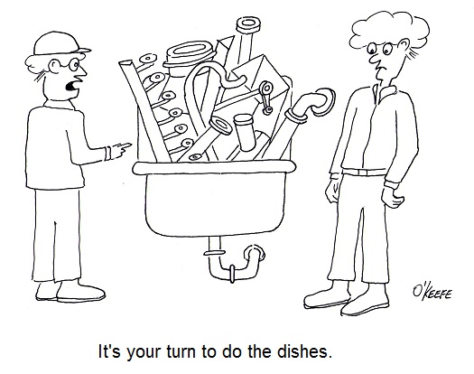
| My wife and I have an agreement concerning the kitchen. She cooks, I clean. Plates and utensils are easy enough to deal with, especially when you have a dishwasher. Pots and pans are a little more challenging. But what I hate the most are the food processors, mixers, blenders, slicers and dicers. They’re designed to make food preparation easier and less time consuming, but they sure don’t make the clean up any easier! Quite frankly, I suspect the time involved to clean them exceeds the time saved in food preparation.
Food processors on a larger scale are also used to manufacture many food products in manufacturing facilities, and being larger and more complicated overall, they’re even more difficult to clean. For example, I once designed a production line incorporating a dough mixer for one of the largest wholesale bakery product suppliers in the United States. A small elevator was required to lift vast amounts of ingredients into a mixing bowl the size of a compact car. Its mixing arms were so heavy, two people were required to lift them into position. It was also my task to ensure that the equipment as designed was capable of being thoroughly cleaned in a timely and cost effective manner.
Food processing machinery must be designed so that all areas coming into contact with ingredients can be readily accessed for cleaning. And since most of the equipment you are dealing with in this setting is far too cumbersome to be portable, the majority of the cleaning must be cleaned in place, known in the industry as CIP. To facilitate CIP, commercial machinery is designed with hatches and special covers that allow workers to get inside with their cleaning equipment. Small, portable parts of the machine, such as pipes, cutting blades, forming mechanisms, and extrusion dies, are often made to be removable so that they can be carried over to an industrial sized sink for cleaning out of place, or COP. These potable machine components are typically removable for COP without the use of any tools and are fitted with flip latches, spring clips, and thumb screws to facilitate the process.
Everything in a food manufacturing facility, from production machinery to conveyor belts, is typically cleaned with hot, pressurized water. The water is ejected from the nozzle end of a hose hooked up to a specially designed valve that mixes steam and cold water. The result is scalding hot pressurized water that easily dislodges food residues. Bacteria doesn’t stand a chance against this barrage. The water, which is maintained at about 180°F, quickly sterilizes everything it makes contact with. It also provides a chemical-free clean that won’t leave behind residues. Once dislodged, debris is flushed out through strategically placed openings in the machine which then empty into nearby floor drains.
As a consequence of the frequent cleanings commercial food preparation machinery requires, their parts must be able to withstand frequent exposure to high pressure water streams. Parts are typically constructed of ultra high molecular weight (UHMW) food-grade plastics and metal alloys such as stainless steels, capable of withstanding the corrosive effects of water. And since water and electricity make a dangerous combination, gaskets and seals on the equipment must be tight enough to protect against water making its way into motors and other electrical parts.
Next time we’ll look at how design engineers of food manufacturing equipment use a systematic approach to minimize the possibility of food safety hazards, such as product contamination.
____________________________________________
|
Tags: bacteria, bakery product, blender, CIP, clean in place, clean out of place, cleanliness, commercial machinery, conveyor belt, COP, corrosion, cover, design engineer, dough, drain, electrical part, electricity, elevator, engineering expert witness, extrusion die, food manufacturer, food manufacturing, food processing equipment, food processing machinery, food processor, food production line, forensic engineer, forming mechanism, gasket, hatch, high pressure hot water, latch, mixer, mixing arm, mixing bowl, mixing valve, nozzle, product contamination, safety hazard, sanitary piping, seal, spring clip, stainless steel, steam, sterilization, thumb screw, UHMW, ultra high molecular weight plastic
Posted in Engineering and Science | Comments Off on Food Manufacturing Challenges – Cleanliness


