| Back in the 60s my dad spent about $25 to buy a small transistor radio. That was a lot of money in those days, but well worth it. The new transistor technology allowed for a much less cumbersome radio to be produced. No more lugging around big radios armed with heavy vacuum tubes. In the years that followed the word transistor became a household word. They were employed in a variety of ways within televisions and other electronic devices, increasing both their reliability and functionality.
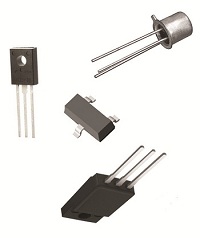
So what is a transistor and what does it do? It’s an electronic component, developed in the late 1940s. The first transistor was about as big as a softball and crudely made. As such, it was too impractical for commercial use. Then in the l950s technological advancements made commercial production of smaller, high-quality transistors possible. Transistors enjoyed widespread introduction to the consuming mainstream in the l960s, and since then they’ve been made in many different types, shapes, and sizes. Some are shown in Figure 1 below. Figure 1
A commonly used type of transistor is called a field effect transistor, or FET, one of which is shown in Figure 2. The FET has three metal leads which allow it to be connected into electrical circuits. These leads are referred to as the drain (D), the source (S), and the gate (G). Figure 2
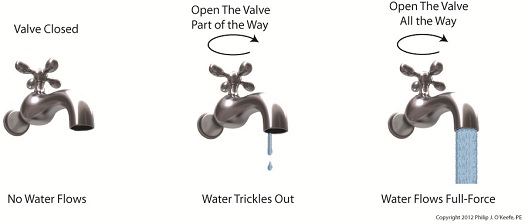
FET’s control the flow of current within an electronic circuit. A good way to understand what they do is to consider the analogy of water flowing through a faucet. Figure 3
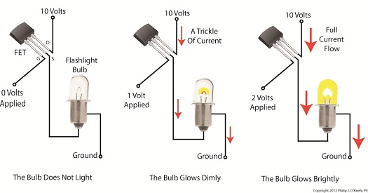
Figure 3 shows a faucet, complete with valve and handle. With the valve closed the flow of water is completely shut off. If the valve is opened partway by rotation of the handle, a trickle of water emerges. The more the handle is turned and valve is opened, the greater the flow of water. The FET shown in Figure 4 operates a lot like a faucet, but with regard to electrical current. Figure 4
The FET controls the flow of current flowing through its D and S leads, but it does not employ a valve or handle to do it. Rather, flow rate is controlled by application of a small amount of voltage to the G lead. The voltage’s influence on the G lead influences the FET to permit current to flow in through the D lead, then out through the S lead. The amount of voltage applied to the G lead is directly related to how much current will be allowed to flow. In this example the D lead on the FET is connected to a 10 volt direct current (VDC) power supply. The S lead is connected to a flashlight bulb which is connected to electrical ground. If you will remember from previous blogs, electric current naturally wants to flow from the supply source to ground, much like water wants to naturally flow downhill. If the bulb was connected directly to the 10 VDC power supply, current would flow through unimpeded and the bulb would light. However, in Figure 4 the FET acts as a regulating device. It’s connected between the 10 VDC power supply and the bulb. When no voltage is applied to the G lead the FET acts like a closed valve and current is unable to flow. Without current we, of course, have no light. When a low amount of voltage, say one volt, is applied to the G lead, the FET acts like a partially opened valve. It permits a trickle of current to flow from the 10 VDC supply to the bulb, and the bulb glows dimly. As voltage to G increases the FET valve opens further, permitting more current to flow. The bulb glows with increasing brightness. When the voltage applied to G increases to the point the FET valve is opened fully, in our example that is 2 volts, full current is allowed to flow from the 10 VDC supply to the bulb. The bulb glows brightly. Generally speaking, the voltage required to be applied to G for control of current flow through an FET depends on overall design and the particular application within an electrical circuit. FETs are often used within electronic devices to turn things on and off, with no other function in between. Next time we’ll look at some example circuits to see how it’s done. ____________________________________________ |
Posts Tagged ‘bulb’
Transistors
Sunday, June 10th, 2012Tags: bulb, current, current flow, drain, electric circuit, electronic circuit, electronic device, electronics, engineering expert witness, FET, field effect transistor, forensic engineer, gate, ground, leads, metal oxide field effect transistor, MOSFET, regulating device, source, supply voltage, switch, valve, voltage, water flow analogy
Posted in Engineering and Science, Expert Witness, Forensic Engineering, Innovation and Intellectual Property, Personal Injury, Product Liability | Comments Off on Transistors
Industrial Control Basics – Electric Relay Ladder Diagram
Sunday, January 22nd, 2012| My daughter will be studying for her driver’s license exam soon, and I can already hear the questions starting. “What does that sign mean? Why does this sign mean construction is ahead?” Symbols are an important part of our everyday lives, and in order to pass her test she’s going to become familiar with dozens of them that line our highways.
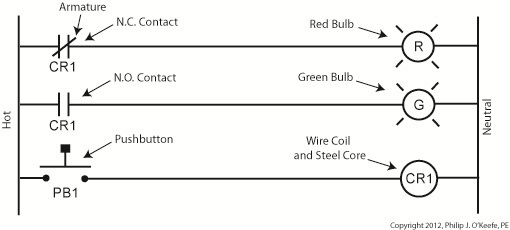
Just as a triangle on the highway is a symbol for “caution,” industrial control systems employ a variety of symbols in their diagrams. The pictures are shorthand for words. They simplify the message, just as hieroglyphics did for our early ancestors who had not yet mastered the ability to write. Ladder diagrams and the abstract symbols used in them are unique to industrial control systems, and they result in faster, clearer interpretations of how the system operates. Last week we analyzed an electric circuit to see what happens when we put a relay to use within a basic industrial control system, as found in Figure 1. Figure 1Now let’s see how it looks in an even simpler form, the three-rung ladder diagram shown in Figure 2. Figure 2In industrial control terminology the electric relays shown in ladder diagrams are often called “control relays,” denoted as CR. Since a ladder diagram can typically include many different control relays, they are numbered to avoid confusion. The relay shown in Figure 2 has been named “CR1.” Our ladder diagram contains a number of symbols. The symbol on the top rung which looks like two parallel vertical lines with a diagonal line bridging the gap between them represents the N.C. contact. This symbol’s vertical lines represent an air gap in the N.C. contact, the diagonal line is the relay armature which performs the function of bridging/closing the air gap. This rung of the ladder diagram represents the contact when the relay is in its normal state. In the middle ladder rung the N.O. contact symbol looks like two parallel vertical lines separated by a gap. There is no diagonal line running through it since the relay armature doesn’t touch the N.O. contact when this particular relay is in its normal state. The wire coil and steel core of this relay are represented by a circle on the bottom ladder rung. The contact and coil symbols on all three rungs are labeled “CR1” to make it clear that they are part of the same control relay. Other symbols within Figure 2 represent the red and green bulbs we have become familiar with from our initial illustration. They are depicted as circles, R for red and G for green, with symbolic light rays around them. The pushbutton, PB1, is represented as we have discussed in previous articles on ladder diagrams. Just as road sign symbols are faster than sentences for drivers speeding down a highway to interpret, ladder diagrams are faster than customary illustrations for busy workers to interpret. Next time we’ll expand on our electric relay by introducing latching components into the control system that will allow for a greater degree of automation. ____________________________________________ |
Tags: armature, automation engineer, bulb, contact, control relay, controls engineer, CR, electric relay, electrical contact, engineering expert witness, forensic engineer, hot, industrial automation, industrial control, ladder diagram, ladder diagram symbol, ladder logic, N.C. contact, N.O. contact, NC contact, neutral, NO contact, normal state, normally closed, normally open, pushbutton, relay, rung, steel core, wire coil
Posted in Engineering and Science, Expert Witness, Forensic Engineering, Innovation and Intellectual Property, Personal Injury, Product Liability, Professional Malpractice | 2 Comments »
Industrial Control Basics – Electric Relay Example
Saturday, January 14th, 2012| When a starving monkey is faced with two buttons, one representing access to a banana, the other cocaine, which will he push? The cocaine, every time. The presence of buttons usually indicates a choice must be made, and electric relays illustrate this dynamic.
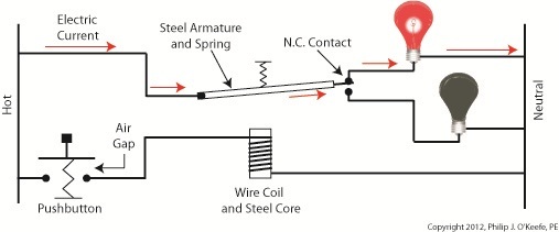
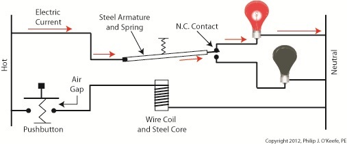
Last week we looked at a basic electric relay and saw how it was used to facilitate a choice in electricity flow between two paths in a circuit. Now let’s see what happens when we put a relay to use within a basic industrial control system making use of lit bulbs. Figure 1
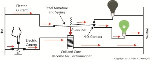
Figure 1 shows an electric relay that’s connected to both hot and neutral wires. At the left side is our pushbutton and the hot wire, on the right two bulbs, one lit, one not, and the neutral wire. No one is depressing the pushbutton, so an air gap exists, preventing current from flowing through the wire coil between the hot and neutral sides. With these conditions in place the relay is said to be in its “normal state.” The relaxed spring positioned on the relay armature keeps it touching the N.C. contact. This allows current to flow between hot and neutral through the armature and the N.C. contact. When these conditions exist the red bulb is lit, and this is accomplished without the need for anyone to throw a switch or press a button. In this condition the other lamp will remain disengaged and unlit. Now let’s refer to Figure 2 to see what happens when someone presses the button. Figure 2
When the button is depressed the air gap is eliminated and the coil and wire become magnetized. They will attract the steel armature closer to them, the spring to expand, and the armature to engage with the N.O. contact. Under these conditions current will no longer flow along a path to light the red bulb because an air gap has been created between the armature and N.C. contact. The current instead flows through the N.O. contact, lighting the green bulb. It will stay lit so long as someone holds the button down. If our monkey were faced with the scenarios presented in Figures l and 2 and a banana was placed in the position of the red bulb, the cocaine in the position of the green, he might find that the regular delivery of bananas that takes place when the relay is in the N.C. contact position is enough to keep him happy. In this state he might be so full of bananas he won’t want to expend the energy to engage the button into the N.O. contact position for the delivery of cocaine. Next time we’ll revisit the subject of ladder diagrams and see how they are used to denote the paths of electric relays. ____________________________________________ |
Tags: armature, bulb, coil, electric circuit, electric current, electric relay example, electricity flow, electro-mechanical relay, electromagnet, engineering expert witness, forensic engineer, hot, hot wire, industrial control, lamp, N.C. contact, N.O. contact, NC contact, neutral, neutral wire, NO contact, normal state, normally closed contact, normally open contact, pushbutton, relay, spring, switch, wire coil
Posted in Engineering and Science, Expert Witness, Forensic Engineering, Innovation and Intellectual Property, Personal Injury, Product Liability, Professional Malpractice | 1 Comment »
