| Back in the 60s my dad spent about $25 to buy a small transistor radio. That was a lot of money in those days, but well worth it. The new transistor technology allowed for a much less cumbersome radio to be produced. No more lugging around big radios armed with heavy vacuum tubes. In the years that followed the word transistor became a household word. They were employed in a variety of ways within televisions and other electronic devices, increasing both their reliability and functionality.
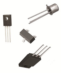
So what is a transistor and what does it do? It’s an electronic component, developed in the late 1940s. The first transistor was about as big as a softball and crudely made. As such, it was too impractical for commercial use. Then in the l950s technological advancements made commercial production of smaller, high-quality transistors possible. Transistors enjoyed widespread introduction to the consuming mainstream in the l960s, and since then they’ve been made in many different types, shapes, and sizes. Some are shown in Figure 1 below. Figure 1
A commonly used type of transistor is called a field effect transistor, or FET, one of which is shown in Figure 2. The FET has three metal leads which allow it to be connected into electrical circuits. These leads are referred to as the drain (D), the source (S), and the gate (G). Figure 2
FET’s control the flow of current within an electronic circuit. A good way to understand what they do is to consider the analogy of water flowing through a faucet. Figure 3
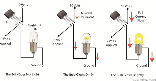
Figure 3 shows a faucet, complete with valve and handle. With the valve closed the flow of water is completely shut off. If the valve is opened partway by rotation of the handle, a trickle of water emerges. The more the handle is turned and valve is opened, the greater the flow of water. The FET shown in Figure 4 operates a lot like a faucet, but with regard to electrical current. Figure 4
The FET controls the flow of current flowing through its D and S leads, but it does not employ a valve or handle to do it. Rather, flow rate is controlled by application of a small amount of voltage to the G lead. The voltage’s influence on the G lead influences the FET to permit current to flow in through the D lead, then out through the S lead. The amount of voltage applied to the G lead is directly related to how much current will be allowed to flow. In this example the D lead on the FET is connected to a 10 volt direct current (VDC) power supply. The S lead is connected to a flashlight bulb which is connected to electrical ground. If you will remember from previous blogs, electric current naturally wants to flow from the supply source to ground, much like water wants to naturally flow downhill. If the bulb was connected directly to the 10 VDC power supply, current would flow through unimpeded and the bulb would light. However, in Figure 4 the FET acts as a regulating device. It’s connected between the 10 VDC power supply and the bulb. When no voltage is applied to the G lead the FET acts like a closed valve and current is unable to flow. Without current we, of course, have no light. When a low amount of voltage, say one volt, is applied to the G lead, the FET acts like a partially opened valve. It permits a trickle of current to flow from the 10 VDC supply to the bulb, and the bulb glows dimly. As voltage to G increases the FET valve opens further, permitting more current to flow. The bulb glows with increasing brightness. When the voltage applied to G increases to the point the FET valve is opened fully, in our example that is 2 volts, full current is allowed to flow from the 10 VDC supply to the bulb. The bulb glows brightly. Generally speaking, the voltage required to be applied to G for control of current flow through an FET depends on overall design and the particular application within an electrical circuit. FETs are often used within electronic devices to turn things on and off, with no other function in between. Next time we’ll look at some example circuits to see how it’s done. ____________________________________________ |
Engineering Expert Witness Blog
Published by Philip J. O'Keefe, PE, MLE
Search
Engineering Expert Witness Services
 Engineering Expert Witness Blog
- Energy Going up in Smoke Through the Stack
- Uncontrollable Factors In Coal Fired Power Plants
- The Depositor’s Industrial Control System
- The Solenoid Valve Operates a Pneumatic Actuator
- The Solenoid Valve’s Operation
- The Solenoid Valve’s Components
- The Depositor’s Scotch Yoke Motion
- The Depositor’s Scotch Yoke
- The Depositor’s Pneumatically Actuated Pump
- The Depositor’s Pneumatic Actuator
Pages
Archives
- September 2018
- August 2018
- July 2018
- June 2018
- May 2018
- April 2018
- March 2018
- February 2018
- January 2018
- December 2017
- November 2017
- October 2017
- September 2017
- August 2017
- July 2017
- June 2017
- May 2017
- April 2017
- March 2017
- February 2017
- January 2017
- December 2016
- November 2016
- October 2016
- September 2016
- August 2016
- July 2016
- June 2016
- May 2016
- April 2016
- March 2016
- February 2016
- January 2016
- December 2015
- November 2015
- October 2015
- September 2015
- August 2015
- July 2015
- June 2015
- May 2015
- April 2015
- March 2015
- February 2015
- January 2015
- December 2014
- November 2014
- October 2014
- September 2014
- August 2014
- July 2014
- June 2014
- May 2014
- April 2014
- March 2014
- February 2014
- January 2014
- December 2013
- November 2013
- October 2013
- September 2013
- August 2013
- July 2013
- June 2013
- May 2013
- April 2013
- March 2013
- February 2013
- January 2013
- December 2012
- November 2012
- October 2012
- September 2012
- August 2012
- July 2012
- June 2012
- May 2012
- April 2012
- March 2012
- February 2012
- January 2012
- December 2011
- November 2011
- October 2011
- September 2011
- August 2011
- July 2011
- June 2011
- May 2011
- April 2011
- March 2011
- February 2011
- January 2011
- December 2010
- November 2010
- October 2010
- September 2010
- August 2010
- July 2010
- June 2010
- May 2010
- April 2010
- March 2010
- February 2010
- January 2010
- December 2009
- November 2009
- October 2009
- September 2009
- August 2009
- July 2009
Calendar
July 2024 M T W T F S S « Sep 1 2 3 4 5 6 7 8 9 10 11 12 13 14 15 16 17 18 19 20 21 22 23 24 25 26 27 28 29 30 31 Admin
The Author...
Engineering Expert Witness Blog is proudly powered by
WordPress
Entries (RSS)
and Comments (RSS).
