Posts Tagged ‘switch’
Monday, July 23rd, 2018
|
So far in this series of articles, we have talked about pneumatic actuators that move jelly filling through a depositor on a pastry production line in a food manufacturing plant. These actuators have pistons with piston rods that create linear motion. The direction of this motion depends on which side compressed air is admitted to the piston inside the actuator. Now, let’s begin discussing a device known to engineers as a solenoid valve. These valves are used to selectively admit compressed air to either side of the pneumatic actuator’s piston, and thus, change the direction of the actuator’s linear motion.
As a solenoid valve’s name implies, a key component is a solenoid. A solenoid consists of a tube, having a coil of wire wrapped around its exterior. Electrical wires extend from the coil to an electrical switch and a voltage supply of, for example, 120 Volts. Inside the tube, there is a steel plunger that is free to move. When the switch is open, the coil is de-energized. That is, no electric current flows from the voltage supply through the coil of wire.
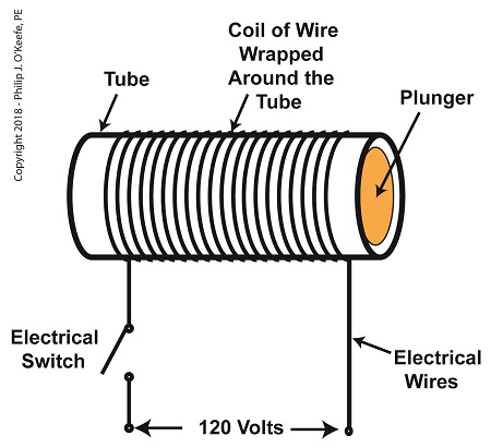
A De-Energized Solenoid
When the electrical switch is closed, the coil becomes energized. As electrical current flows through the coil, a magnetic field is created in the tube. This field forces the steel plunger out of the tube. The magnetic field and force on the plunger remain as long as the switch is closed.
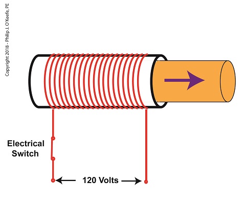
An Energized Solenoid
A solenoid valve consists of a solenoid that is attached to a metal valve body. The solenoid is typically enclosed in a plastic or metal housing. The valve body contains various ports. The ports are threaded holes for the connection of compressed air pipes.
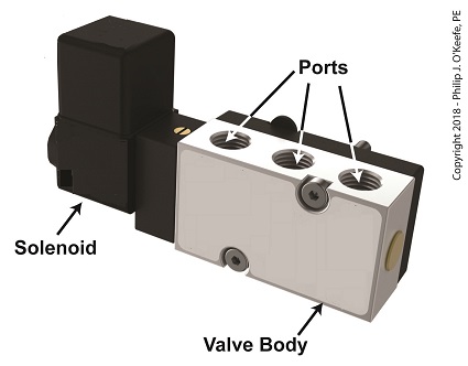
A Solenoid Valve
The solenoid’s plunger is attached to spool in the valve body. The spool is free to move within the valve body past passage ways extending from the ports. In the following illustration, the solenoid valve contains five ports, designated A through E.
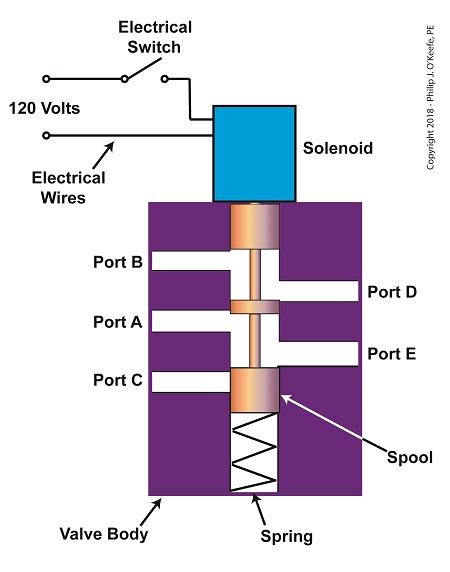
The Solenoid Valve’s Components
Next time we’ll see how the five port solenoid valve operates to create different compressed air flow paths between its ports.
Copyright 2018 – Philip J. O’Keefe, PE
Engineering Expert Witness Blog
____________________________________ |
Tags: coil, compressed air, depositor, engineers, food manufacturing, jelly filling, magnetic field, pastry line, plunger, port, solenoid, solenoid valve, spool, switch, valve body, voltage source
Posted in Engineering and Science, Expert Witness, Forensic Engineering, Innovation and Intellectual Property, Personal Injury, Product Liability, Professional Malpractice | Comments Off on The Solenoid Valve’s Components
Monday, June 18th, 2012
| In the navy, the captain is the brains behind a ship’s operations. He gathers information, makes important decisions, then issues orders. He’s not there to roll up his sleeves and swab the decks. The captain relies on the ship’s officers to act as an interface between himself and the sailors that perform the physical labor required on deck.
In this article we’ll see how the FET, that is, the field effect transistor, performs much the same role as the ship’s officers when it is used within electronic controls. There it acts as an interface between electronic components that issue commands and the electrical devices that carry them out.
Last week we became familiar with field effect transistors and how their control of electrical current flow is analogous to how a faucet controls the flow of water. Although FETs can be used to vary the flow of current, they’re usually employed to perform a much simpler task, that of simply turning flow on or off, with no in-between modality.
Like the captain of a ship, microprocessor and logic chips are the brains behind the operation in all sorts of industrial and consumer electronics. Figure 1 shows a few of them.

Figure 1
The chips, which operate on low voltage, contain entire computer programs within them that gather information, make decisions, then instruct the higher voltage devices like motors, electrical relays, light bulbs, and audible alarms to follow. By “information,” I mean data signals received by the chip from its input connections to sensors, buttons, and other electrical components. This data informs the chip’s computer program of important operational information, like whether buttons have been pressed, switches are activated, and temperatures are normal. Based on this data, “decisions” are made by the chip using the logic contained within its program, then, depending on the decisions made, “commands” are issued by the chip. The commands, in the form of electrical output signals, are put into action by the work horses, the higher voltage devices. They, like a ship’s sailors, perform the actual physical work.
There is one problem presented by this scenario, however. The electric output signals from the lower voltage chips are not suited to directly control the higher voltage devices because the signal voltage put out by the chips is too low. Even if the chip was designed to work at a higher voltage, the high level of current drawn by the motors, relays, and bulbs would lead to damage of the delicate circuitry within the chip. The chips must therefore rely on the FET to act as a digital control interface between them and the higher voltage devices, much as the ship’s captain depends on his subordinates to carry out his orders.
Next week we’ll look at a real life example of how a digital interface is put into operation within an industrial product.
____________________________________________
|
Tags: audible alarms, computer program, current flow, data signals, digital chips, digital electronics, digital interface, electric current, electric relay, electrical output signal, electronic components, electronic controls, engineering expert witness, FET, field effect transistor, forensic engineer, high voltage, industrial and consumer electronics, industrial product, light bulb, logic chips, low voltage, microprocessor, motors, switch, transistor
Posted in Engineering and Science, Expert Witness, Forensic Engineering, Innovation and Intellectual Property, Personal Injury, Product Liability | Comments Off on Transistors – Digital Control Interface, Part I
Sunday, June 10th, 2012
| Back in the 60s my dad spent about $25 to buy a small transistor radio. That was a lot of money in those days, but well worth it. The new transistor technology allowed for a much less cumbersome radio to be produced. No more lugging around big radios armed with heavy vacuum tubes. In the years that followed the word transistor became a household word. They were employed in a variety of ways within televisions and other electronic devices, increasing both their reliability and functionality.
So what is a transistor and what does it do? It’s an electronic component, developed in the late 1940s. The first transistor was about as big as a softball and crudely made. As such, it was too impractical for commercial use. Then in the l950s technological advancements made commercial production of smaller, high-quality transistors possible. Transistors enjoyed widespread introduction to the consuming mainstream in the l960s, and since then they’ve been made in many different types, shapes, and sizes. Some are shown in Figure 1 below.

Figure 1
A commonly used type of transistor is called a field effect transistor, or FET, one of which is shown in Figure 2. The FET has three metal leads which allow it to be connected into electrical circuits. These leads are referred to as the drain (D), the source (S), and the gate (G).

Figure 2
FET’s control the flow of current within an electronic circuit. A good way to understand what they do is to consider the analogy of water flowing through a faucet.

Figure 3
Figure 3 shows a faucet, complete with valve and handle. With the valve closed the flow of water is completely shut off. If the valve is opened partway by rotation of the handle, a trickle of water emerges. The more the handle is turned and valve is opened, the greater the flow of water.
The FET shown in Figure 4 operates a lot like a faucet, but with regard to electrical current.

Figure 4
The FET controls the flow of current flowing through its D and S leads, but it does not employ a valve or handle to do it. Rather, flow rate is controlled by application of a small amount of voltage to the G lead. The voltage’s influence on the G lead influences the FET to permit current to flow in through the D lead, then out through the S lead. The amount of voltage applied to the G lead is directly related to how much current will be allowed to flow.
In this example the D lead on the FET is connected to a 10 volt direct current (VDC) power supply. The S lead is connected to a flashlight bulb which is connected to electrical ground. If you will remember from previous blogs, electric current naturally wants to flow from the supply source to ground, much like water wants to naturally flow downhill.
If the bulb was connected directly to the 10 VDC power supply, current would flow through unimpeded and the bulb would light. However, in Figure 4 the FET acts as a regulating device. It’s connected between the 10 VDC power supply and the bulb. When no voltage is applied to the G lead the FET acts like a closed valve and current is unable to flow. Without current we, of course, have no light.
When a low amount of voltage, say one volt, is applied to the G lead, the FET acts like a partially opened valve. It permits a trickle of current to flow from the 10 VDC supply to the bulb, and the bulb glows dimly. As voltage to G increases the FET valve opens further, permitting more current to flow. The bulb glows with increasing brightness.
When the voltage applied to G increases to the point the FET valve is opened fully, in our example that is 2 volts, full current is allowed to flow from the 10 VDC supply to the bulb. The bulb glows brightly. Generally speaking, the voltage required to be applied to G for control of current flow through an FET depends on overall design and the particular application within an electrical circuit.
FETs are often used within electronic devices to turn things on and off, with no other function in between. Next time we’ll look at some example circuits to see how it’s done.
____________________________________________ |
Tags: bulb, current, current flow, drain, electric circuit, electronic circuit, electronic device, electronics, engineering expert witness, FET, field effect transistor, forensic engineer, gate, ground, leads, metal oxide field effect transistor, MOSFET, regulating device, source, supply voltage, switch, valve, voltage, water flow analogy
Posted in Engineering and Science, Expert Witness, Forensic Engineering, Innovation and Intellectual Property, Personal Injury, Product Liability | Comments Off on Transistors
Saturday, January 14th, 2012
| When a starving monkey is faced with two buttons, one representing access to a banana, the other cocaine, which will he push? The cocaine, every time. The presence of buttons usually indicates a choice must be made, and electric relays illustrate this dynamic.
Last week we looked at a basic electric relay and saw how it was used to facilitate a choice in electricity flow between two paths in a circuit. Now let’s see what happens when we put a relay to use within a basic industrial control system making use of lit bulbs.

Figure 1
Figure 1 shows an electric relay that’s connected to both hot and neutral wires. At the left side is our pushbutton and the hot wire, on the right two bulbs, one lit, one not, and the neutral wire. No one is depressing the pushbutton, so an air gap exists, preventing current from flowing through the wire coil between the hot and neutral sides. With these conditions in place the relay is said to be in its “normal state.”
The relaxed spring positioned on the relay armature keeps it touching the N.C. contact. This allows current to flow between hot and neutral through the armature and the N.C. contact. When these conditions exist the red bulb is lit, and this is accomplished without the need for anyone to throw a switch or press a button. In this condition the other lamp will remain disengaged and unlit.
Now let’s refer to Figure 2 to see what happens when someone presses the button.

Figure 2
When the button is depressed the air gap is eliminated and the coil and wire become magnetized. They will attract the steel armature closer to them, the spring to expand, and the armature to engage with the N.O. contact. Under these conditions current will no longer flow along a path to light the red bulb because an air gap has been created between the armature and N.C. contact. The current instead flows through the N.O. contact, lighting the green bulb. It will stay lit so long as someone holds the button down.
If our monkey were faced with the scenarios presented in Figures l and 2 and a banana was placed in the position of the red bulb, the cocaine in the position of the green, he might find that the regular delivery of bananas that takes place when the relay is in the N.C. contact position is enough to keep him happy. In this state he might be so full of bananas he won’t want to expend the energy to engage the button into the N.O. contact position for the delivery of cocaine.
Next time we’ll revisit the subject of ladder diagrams and see how they are used to denote the paths of electric relays.
____________________________________________ |
Tags: armature, bulb, coil, electric circuit, electric current, electric relay example, electricity flow, electro-mechanical relay, electromagnet, engineering expert witness, forensic engineer, hot, hot wire, industrial control, lamp, N.C. contact, N.O. contact, NC contact, neutral, neutral wire, NO contact, normal state, normally closed contact, normally open contact, pushbutton, relay, spring, switch, wire coil
Posted in Engineering and Science, Expert Witness, Forensic Engineering, Innovation and Intellectual Property, Personal Injury, Product Liability, Professional Malpractice | 1 Comment »
Monday, January 9th, 2012
| It’s a dark and stormy night and you’ve come to the proverbial fork in the road. The plot is about to take a twist as you’re forced to make a decision in this either/or scenario. As we’ll see in this article, an electric relay operates in much the same manner, although choices will be made in a forced mechanical environment, not a cerebral one.
When we discussed basic electric relays last week we talked about their resting in a so-called “normal state,” so designated by industrial control parlance. It’s the state in which no electric current is flowing through its wire coil, the coil being one of the major devices within a relay assembly. Using Figure 3 of my previous article as a general reference, in this normal state a relaxed spring keeps the armature touching the N.C. switch contact. While in this state, a continuous conductive path is created for electricity through to the N.C. point. It originates from the wire on the left side, which leads to the armature pivot point, travels through the armature and N.C. contact points, and finally dispenses through the wire at the right leading from the N.C. contact.
Now let’s look at an alternate scenario, when current is made to flow through the coil. See Figure l, below.

Figure 1
Figure 1 shows the path of electric current as it flows through the wire coil, causing the coil and the steel core to which it’s attached to become magnetized. This magnetization is strong, attracting the steel armature and pulling it towards the steel core, thus overcoming the spring’s tension and its natural tendency to rest in a tension-free state.
The magnetic attraction causes the armature to rotate about the pivot point until it comes to rest against the N.O. contact, thus creating an electrical path en route to the N.O. wire, on its way to whatever device it’s meant to energize. As long as current flows through the wire coil, its electromagnetic nature will attract the armature to it and contact will be maintained with the N.O. juncture.
When current is made to flow through the wire coil, an air gap is created between the armature and the N.C. contact, and this prevents the flow of electric current through the N.C. contact area. Current is forced to follow the path to the N.O. contact only, effectively cutting off any other choice or fork in the road as to electrical path that may be followed. We can see that the main task of an electric relay is to switch current between two possible paths within a circuit, thereby directing its flow to one or the other.
Next time we’ll examine a simple industrial control system and see how an electric relay can be engaged with the help of a pushbutton.
____________________________________________ |
Tags: armature, coil, control relay, control system, current flow, electric current, electric relay, electrical path, electrical relay, electrical switch, electricity, electromagnetic, engineering expert witness, forensic engineering, industrial control, magnetic attraction, N.C., N.C. contact, N.O., N.O. contact, normal state, normally closed, normally open, pushbutton, relay, relay ladder logic, spring, steel core, switch, switch contact, switching current, wire coil
Posted in Engineering and Science, Expert Witness, Forensic Engineering, Innovation and Intellectual Property, Personal Injury, Product Liability, Professional Malpractice | 1 Comment »
Tuesday, January 3rd, 2012
| I’ve always considered science to be cool. Back in the 5th grade I remember fondly leafing through my science textbook, eagerly anticipating our class performing the experiments, but we never did. For some reason my teacher never took the time to demonstrate any. Undeterred, I proceeded on my own.
I remember one experiment particularly well where I took a big steel nail and coiled wire around it. When I hooked a battery up to the wires, as shown in Figure 1 below, electric current flowed from the battery through the wire coil. This set up a magnetic field in the steel nail, thereby creating an electromagnet. My electromagnet was strong enough to pick up paper clips, and I took great pleasure in repeatedly picking them up, then watching them unattach and fall quickly away when the wires were disconnected from the battery.

Figure 1
Little did I know then that the electromagnet I had created was similar to an important part found within electrical relays used in many industrial control systems. An example of one of these relays is shown in Figure 2.

Figure 2
So, what’s in the little plastic cube? Well, a relay is basically an electric switch, similar to the ones we’ve discussed in the past few weeks, the major difference being that it is not operated directly by human hands. Rather, it’s operated by an electromagnet. Let’s see how this works by examining a basic electrical relay, as shown in Figure 3.

Figure 3
The diagram in Figure 3 shows a basic electric relay constructed of a steel core with a wire coil wrapped around it, similar to the electromagnet I constructed in my 5th grade experiment. If the coil’s wires are not hooked up to a power source, a battery for example, no electric current will flow through it. When there is no current the coil and steel core are not magnetic. For purposes of our illustration and in accordance with industrial control parlance, this is said to be this relay’s “normal state.”
Next to the steel core there is a movable steel armature, a kind of lever, which is attached to a spring. On one end of the armature is a pivot point, on the other end is a set of electrical switch contacts. When the relay is in its normal state, the spring’s tension holds the armature against the “normally closed,” or N.C., contact. If electric current is applied to the wire leading to the pivot point on the armature while in this state, it will be caused to flow on a continuous path through the armature and the N.C. contact, then out through the wire leading from the N.C. contact. In our illustration, since the armature does not touch the N.O. contact, an air gap is created that prevents electric current from traveling through the contact from the armature.
Next week we’ll see how these parts come into play within a relay when electric current flows through the coil, turning it into an electromagnet.
____________________________________________ |
Tags: armature, control system, electric current, electric relay, electrical switch contacts, electromagnet, electromechanical relay, engineering expert witness, forensic engineer, industrial control, magnet, magnetic steel core, normal state, normally closed, normally open, power, relay, relay logic, spring, steel core, switch, switch contact, wire, wire coil
Posted in Engineering and Science, Expert Witness, Forensic Engineering, Innovation and Intellectual Property, Personal Injury, Product Liability, Professional Malpractice | Comments Off on Industrial Control Basics – Introduction to Electric Relays
Monday, December 26th, 2011
| I always enjoy watching impatient people waiting for an elevator. They press the button, and if it doesn’t come within a few seconds they press it over and over again, as if this will hurry things up. In the end they must resign themselves to the fact that the elevator will operate in its own good time.
Pushbuttons, although simple in appearance like the big, red “Easy” button that’s featured in a certain business supply chain’s commercials, are actually complex behind the scenes. They perform important functions within the industrial control systems of a huge diversity of mechanized equipment.
Last week we introduced ladder diagrams, used to design and document industrial control systems, and we’ll now see how they depict the action of pushbuttons within two commonly used industrial settings, the “normally open” and the “normally closed.”

Figure 1
Figure 1(a) shows a pushbutton hooked up to an electric motor. When no one is pressing it a spring in the pushbutton forces the button to rest in the up position, allowing an air gap to exist in the electrical circuit between hot and neutral and preventing current from flowing. This type of switch is characterized as a “normally open” switch in industrial control terminology.
In Figure 1(b) someone depresses the button, compressing its spring and closing the air gap, which allows current to flow and the motor to operate
Figure 1(c) shows the ladder diagram version of 1(a).
Now let’s take a look at Figure 2 to see a different type of pushbutton, one that’s characterized as “normally closed.”
 Figure 2 Figure 2
“Normally closed” refers to the fact that when no one is depressing the button, the normal operating position is for the air gap to be absent, allowing electrical current to flow and the motor to operate, as shown in Figure 2(a).
Figure 2(b) shows that an air gap is created when the button is depressed and the spring holding the mechanism into the normally closed position is forced down. This action interrupts electrical current and causes the motor to stop.
Figure 2(c) shows the simplified line drawing version of 2(a).
You can imagine how strained your finger would be if it had to press down on that button with any frequency or duration. Next time we’ll see how electrical relays work alongside pushbuttons to give index fingers a break.
____________________________________________ |
Tags: control system, current flow, electric motor, electrical circuit, engineering expert witness, forensic engineer, hot, industrial control, ladder diagram, machine control, mechanized equipment, motor control, neutral, normally closed, normally open, pushbutton, relay, spring, switch
Posted in Engineering and Science, Expert Witness, Forensic Engineering, Innovation and Intellectual Property, Personal Injury, Product Liability, Professional Malpractice | Comments Off on Industrial Control Basics – Pushbuttons
Sunday, December 4th, 2011
| When I was a child in school I loved field trips. They didn’t happen too often, but when they did they were a welcomed break from the routine of the classroom. Once we went on a tour of a large factory that made telephones. During the tour we walked amongst gargantuan machines, conveyor belts, furnaces, boilers, pumps, and compressors, all energized and working together to transform raw materials into telephones. Sequences of manufacturing and assembly operations, from the simple to the most complex, were carefully orchestrated with no apparent human intervention.
The equipment in the telephone factory was certainly impressive to watch, and our tour guides did a fine job of explaining what was happening, except for one important detail. I realized after we left that no one had explained who or what was actually controlling the machinery. I realized even then that machines can’t think for themselves. They can only do what humans tell them to do.
I didn’t know it at the time, but the telephone factory setup included some interesting examples of industrial control systems. Industrial control systems can be broken down into two basic categories, manual controls and automatic controls. Manual controls work as their name implies, that is, someone must manually press a button or throw a switch to initiate factory operations. This involves continual monitoring of processes, coupled with hands-on activities to keep everything working.
Automatic controls still require human intervention to some extent, such as initiating operations, but once that’s done they move into self-regulation mode until the operations are shut down at the end of production. Employees are thus freed up to spend time doing things which are not automated. Automatic controls are excellent at handling mundane, repetitive tasks that humans tend to get quickly bored with. Boredom leads to a lack of attention, and this may lead to accidents, so utilizing automatic controls often makes for a safer work environment.
Next time we’ll begin our examination of how manual and automatic controls work within the context of an industrial setting. To begin, we’re going to take a virtual field trip back to the telephone factory and look at some basic industrial control examples.
____________________________________________

|
Tags: accidents, automatic control, boilers, button, compressors, controlling machinery, conveyor belt, engineering expert witness, factory, forensic engineer, furnaces, industrial control, machine control, machines, manual control, process monitoring, pumps, switch, telephones
Posted in Engineering and Science, Expert Witness, Forensic Engineering, Innovation and Intellectual Property, Personal Injury, Product Liability, Professional Malpractice | Comments Off on Industrial Control Basics


