Posts Tagged ‘engineers’

The Solenoid Valve Operates a Pneumatic Actuator

Monday, August 6th, 2018

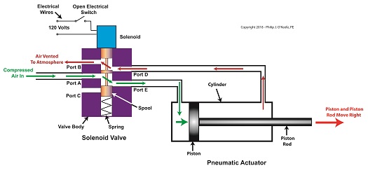
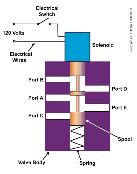
    Last time, we learned how a solenoid valve operates to create different compressed air flow paths through passageways within its valve body.   These different air flow paths are created by opening and closing an electrical switch to de-energize and energize a solenoid mounted on the valve body.   Now let’s see how engineers use a solenoid valve in a food manufacturing plant to move a depositor’s pneumatic actuator piston back and forth with compressed air pressure.

    Consider the pneumatic actuator on the depositor’s scotch yoke.   With the solenoid valve’s electrical switch opened, the valve’s spool is pushed up in the valve body by a spring to create air flow paths between Ports A and E and Ports D and B.   If compressed air is fed into Port A and the left side of the pneumatic actuator’s cylinder is connected to Port E, then the air pressure moves the actuator’s piston to the right.   But, for the actuator piston to move freely to the right, the right side of the cylinder is connected to Port D on the valve body.   As the piston moves to the right, it forces air out of the right side of the cylinder, through Port D, through the valve body, and out through Port B to be vented to the atmosphere.

The De-Energized Solenoid Valve Operates a Pneumatic Actuator

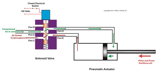
The De-energized Solenoid Valve Operates a Pneumatic Actuator

    With the solenoid valve’s electrical switch closed, the spool is pushed down in the valve body by the solenoid, to create air flow paths between Ports A and D and Ports E and C.   If compressed air is fed into Port A and the right side of the pneumatic actuator’s cylinder is connected to Port D, then the air pressure moves the actuator’s piston to the left.   But, for the actuator piston to move freely to the left, the left side of the cylinder is connected to Port E.   As the piston moves left, air is forced out of the left side of the cylinder, through Port E, and vented to the atmosphere through Port C.

 The Energized Solenoid Valve Operates a Pneumatic Actuator

The Energized Solenoid Valve Operates a Pneumatic Actuator

    So, in review, opening the solenoid valve’s electrical switch causes the pneumatic actuator piston to move right.  Closing the switch causes the piston to move left.   But there is a problem with this setup.   Operating an electrical switch by hand to deposit jelly filling on thousands of pastries can get tiring after a while.   Next time, we’ll see how the valve’s solenoid can be automatically turned on and off by an industrial control system.

Copyright 2018 – Philip J. O’Keefe, PE

Engineering Expert Witness Blog

____________________________________


The Solenoid Valve’s Components

Monday, July 23rd, 2018

    So far in this series of articles, we have talked about pneumatic actuators that move jelly filling through a depositor on a pastry production line in a food manufacturing plant.   These actuators have pistons with piston rods that create linear motion.   The direction of this motion depends on which side compressed air is admitted to the piston inside the actuator.   Now, let’s begin discussing a device known to engineers as a solenoid valve.   These valves are used to selectively admit compressed air to either side of the pneumatic actuator’s piston, and thus, change the direction of the actuator’s linear motion.

    As a solenoid valve’s name implies, a key component is a solenoid.   A solenoid consists of a tube, having a coil of wire wrapped around its exterior.   Electrical wires extend from the coil to an electrical switch and a voltage supply of, for example, 120 Volts.   Inside the tube, there is a steel plunger that is free to move.    When the switch is open, the coil is de-energized.   That is, no electric current flows from the voltage supply through the coil of wire.

 A De-Energized Solenoid

A De-Energized Solenoid


    When the electrical switch is closed, the coil becomes energized. As electrical current flows through the coil, a magnetic field is created in the tube.   This field forces the steel plunger out of the tube.  The magnetic field and force on the plunger remain as long as the switch is closed.

An Energized Solenoid

An Energized Solenoid


    A solenoid valve consists of a solenoid that is attached to a metal valve body.   The solenoid is typically enclosed in a plastic or metal housing.   The valve body contains various ports.   The ports are threaded holes for the connection of compressed air pipes.

A Solenoid Valve

A Solenoid Valve


    The solenoid’s plunger is attached to spool in the valve body.   The spool is free to move within the valve body past passage ways extending from the ports.   In the following illustration, the solenoid valve contains five ports, designated A through E.


The Solenoid Valve’s Components

The Solenoid Valve’s Components


    Next time we’ll see how the five port solenoid valve operates to create different compressed air flow paths between its ports.


Copyright 2018 – Philip J. O’Keefe, PE

Engineering Expert Witness Blog

____________________________________


Using a Free Body Diagram to Understand Simple Pulleys

Thursday, July 21st, 2016

    Sometimes the simplest alteration in design results in a huge improvement, a truth I’ve discovered more than a few times during my years as an engineering expert.   Last time we introduced the simple pulley and revealed that its usefulness was limited to the strength of the pulling force behind it.   Hundreds of years ago that force was most often supplied by a man and his biceps.   But ancient Greeks found an ingenious and simple way around this limitation, which we’ll highlight today by way of a modern design engineer’s tool, the free body diagram.

    Around 400 BC, the Greeks noticed that if they detached the simple pulley from the beam it was affixed to in our last blog and instead allowed it to be suspended in space with one of its rope ends fastened to a beam, the other rope end to a pulling force, something interesting happened.

The Simple Pulley Improved

The Simple Pulley Improved

    It was much easier to lift objects while suspended in air.  As a matter of fact, it took 50% less effort.   To understand why, let’s examine what engineers call a free body diagram of the pulley in our application, as shown in the blue inset box and in greater detail below.

Free Body Diagram of an Improved Simple Pulley

Using a Free Body Diagram to Understand Simple Pulleys

    The blue insert box in the first illustration highlights the subject at hand.   A free body diagram helps engineers analyze forces acting upon a stationary object suspended in space.   The forces acting upon the object, in our case a simple pulley, represent both positive and negative values.   The free body diagram above indicates that forces pointing up are, by engineering convention, considered to be positive, while downward forces are negative.   The basic rule of all free body diagrams is that in order for an object to remain suspended in a fixed position in space, the sum of all forces acting upon it must equal zero.

    We’ll see how the free body diagram concept is instrumental in understanding the improvement upon the action of a simple pulley next time, when we attack the math behind it.

Copyright 2016 – Philip J. O’Keefe, PE

Engineering Expert Witness Blog

____________________________________


Transistors – Voltage Regulation Part XIV

Monday, October 22nd, 2012

     As we’ve come to know through this series of blogs, all electronic components pose some degree of internal resistance to the electric current flowing through them.  This resistance results in electrical energy being converted into heat energy, heat which poses potential problems to sensitive components like electronic circuit boards.  If things get hot enough, components fail and fires may ignite. 

     To address these issues engineers design circuits with resistors whose job it is to limit the current flowing to electrical components.  In this article we’ll see how a limiting resistor protects a Zener diode from this fate, allowing it to continue doing its job of regulating voltage.    

     In our last blog we applied Ohm’s Law to our regulated power supply circuit, which makes use of a Zener diode.  See Figure 1.power supply

Figure 1


     Ohm’s Law gave us the following equation to determine the amount of current, IPS, flowing from the unregulated power supply portion, through the current limiting resistor RLimiting, and making its way into the rest of the circuit:

IPS = (VUnregulatedVZener) ÷ RLimiting

     We learned last week that for the circuit to work, the voltage of the unregulated power supply portion of the circuit, VUnregulated, must be greater than the Zener voltage, VZener.

     Looking at the equation above, we see that the voltage difference is divided by RLimiting, the value of the limiting resistor in the circuit.  This limiting resistor is there to constrain the current flowing to the Zener diode, allowing the diode to keep things under control within the circuit. 

     Basic mathematical principles hold that if a smaller number is divided by a bigger number, the resulting answer is an even smaller number.  Applying this principle to the equation above, if RLimiting is a big number, then IPS must be a smaller number.  On the other hand the smaller RLimiting gets, the bigger IPS becomes. 

     So what does it take for our circuit to fail?  Remove the limiting resistor as shown in Figure 2 and the value for RLimiting disappears.  In other words, RLimiting becomes zero.

zener diode with no limiting resistor

Figure 2


     In this case our Ohm’s Law equation becomes:

IPS = (VUnregulatedVZener) ÷ 0 =

     The resulting answer is said to go to infinity, or , as it is represented mathematically.  In other words, without a limiting resistor being employed within our circuit, IPS will become so large it will overwhelm the diode’s current handling capacity and lead to circuit failure. 

     Next time we’ll go over some advantages and disadvantages of this Zener diode voltage regulating circuit, and why the disadvantages outweigh the advantages for many applications.

____________________________________________