Posts Tagged ‘simple pulley’

Dynamic Lifting is Easier With a Compound Pulley

Friday, October 14th, 2016

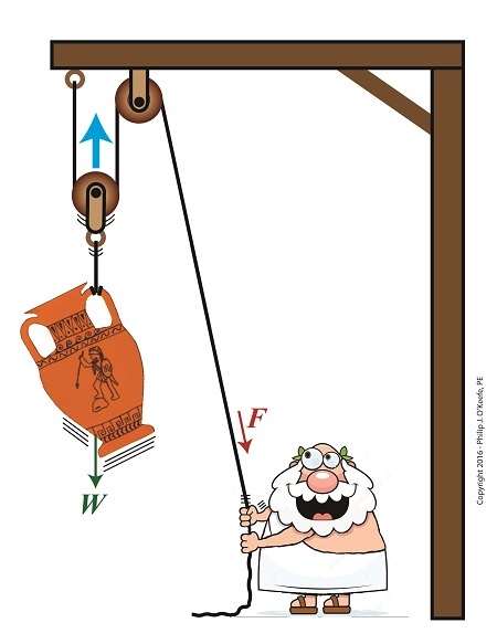
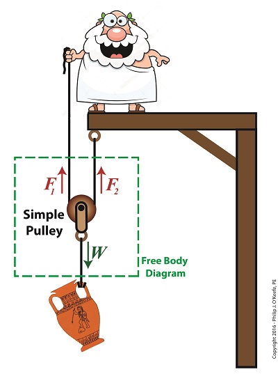
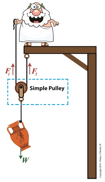
    Last time we introduced the engineering concept of mechanical advantage, MA.   Thanks to its presence in our compound pulley arrangement, it made a Grecian man’s job of holding an urn suspended in space twice as easy as compared to when he used a mere simple pulley.   Today we’ll see what happens when our static scenario becomes active through dynamic lifting and how it affects his efforts.

Dynamic Lifting is Easier With a Compound Pulley

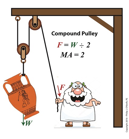
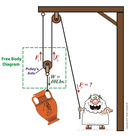
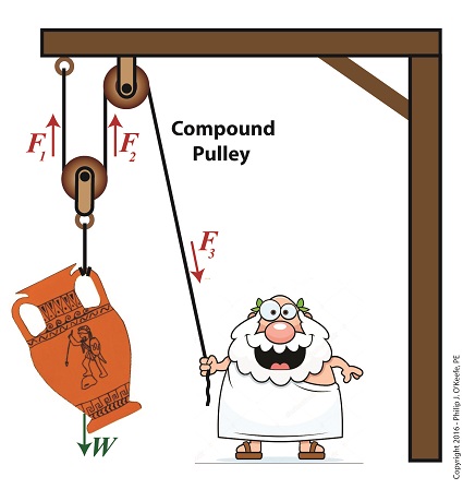
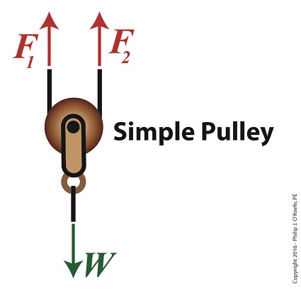
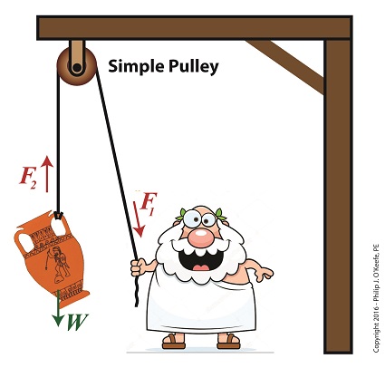
Dynamic Lifting is Easier With a Compound Pulley

    If you’ll recall from our last blog, Mr. Toga used a compound pulley to assist him in holding an urn stationary in space.   To do so, he only needed to exert personal bicep force, F, equivalent to half the urn’s weight force, W, which meant he enjoyed a mechanical advantage of 2.  Mathematically that is represented by,

F = W ÷ 2

If the urn weighs 40 pounds, then he only needs to exert 20 Lbs of personal effort to keep it suspended.

   But when Mr. Toga uses more bicep power with that same compound pulley, he’s able to dynamically raise its position in space until it eventually meets with the beam that supports it.   All the while he’ll be exerting a force greater than W ÷ 2.   That relationship is represented by,

F > W ÷ 2

    In the case of a 40 Lb urn, the lifting force Mr. Toga must exert to dynamically lift the urn is represented by,

F > 40 Lbs ÷ 2

F > 20 Lbs

where F represents a bicep force of at least 20 pounds.   Fortunately for him, his efforts will never have to extend much beyond 20 Lbs of effort to lift the urn to the beam.   That’s because gravity’s effect will remain nearly constant as the urn climbs, this being due to gravity’s influence upon objects decreasing by an insignificant amount over short distances above the Earth’s surface.   As a matter of fact, at an altitude of 3,280 feet, gravity’s pull decreases by a mere 0.2 %.

    The net result is that the compound pulley enables the same mechanical advantage whether a static or dynamic scenario exists, that is, regardless of whether Mr. Toga is simply holding the urn stationary in space or he’s actively tugging on his end of the rope to lift it higher.

    Next time we’ll see how mechanical advantage increases when we add more fixed and moveable pulleys to our compound pulley arrangement.

 Copyright 2016 – Philip J. O’Keefe, PE

Engineering Expert Witness Blog

____________________________________


Mechanical Advantage of a Compound Pulley

Thursday, September 29th, 2016

    In this blog series on pulleys we’ve gone from discussing the simple pulley to the improved simple pulley to an introduction to the complex world of compound pulleys, where we began with a static representation.   We’ve used the engineering tool of a free body diagram to help us understand things along the way, and today we’ll introduce another tool to prepare us for our later analysis of dynamic compound pulleys.   The tool we’re introducing today is the engineering concept of mechanical advantage, MA, as it applies to a compound pulley scenario.

    The term mechanical advantage is used to describe the measure of force amplification achieved when humans use tools such as crowbars, pliers and the like to make the work of prying, lifting, pulling, bending, and cutting things easier.   Let’s see how it comes into play in our lifting scenario.

    During our previous analysis of the simple pulley, we discovered that in order to keep the urn suspended, Mr. Toga had to employ personal effort, or force, equal to the entire weight of the urn.

F = W                                    (1)

    By comparison, our earlier discussion on the static compound pulley revealed that our Grecian friend need only exert an amount of personal force equal to 1/2 the suspended urn’s weight to keep it in its mid-air position.   The use of a compound pulley had effectively improved his ability to suspend the urn by a factor of 2.   Mathematically, this relationship is demonstrated by,

F = W ÷ 2                              (2)

    The factor of 2 in equation (2) represents the mechanical advantage Mr. Toga realizes by making use of a compound pulley.   It’s the ratio of the urn’s weight force, W, to the employed force, F.   This is represented mathematically as,

MA = W ÷                           (3)

    Substituting equation (2) into equation (3) we arrive at the mechanical advantage he enjoys by making use of a compound pulley,

MA = W ÷ (W ÷ 2) = 2           (4)

Mechanical Advantage of a Compound Pulley

Mechanical Advantage of  a Compound Pulley

    Next time we’ll apply what we’ve learned about mechanical advantage to a compound pulley used in a dynamic lifting scenario.


 Copyright 2016 – Philip J. O’Keefe, PE

Engineering Expert Witness Blog

____________________________________


The Math Behind a Static Compound Pulley

Friday, September 9th, 2016

    Last time we introduced the compound pulley and saw how it improved upon a simple pulley, both of which I’ve engaged in my work as an engineering expert.  Today we’ll examine the math behind the compound pulley.   We’ll begin with a static representation and follow up with an active one in our next blog.

    The compound pulley illustrated below contains three rope sections with three representative tension forces, F1, F2, and F3.   Together, these three forces work to offset the weight, W, of a suspended urn weighing 40 lbs.   Weight itself is a downward pulling force due to the effects of gravity.

    To determine how our pulley scenario affects the man holding his section of rope and exerting force F3, we must first calculate the tension forces F1 and F2.   To do so, we’ll use a free body diagram, shown in the green box, to display the forces’ relationship to one another.

A Compound Pulley

The Math Behind a Static Compound Pulley

    The free body diagram only takes into consideration the forces inside the green box, namely F1, F2, and W.

    For the urn to remain suspended stationary in space, we know that F1 and F2 are each equal to one half the urn’s weight, because they’re spaced equidistant from the pulley’s axle, which directly supports the weight of the urn.  Mathematically this looks like,

F1 = F2 = W ÷ 2

    Because we know F1 and F2, we also know the value of F3, thanks to an engineering rule concerning pulleys.  That is, when a single rope is used to support an object with pulleys, the tension force in each section of rope must be equal along the entire length of the rope, which means F1 = F2 = F3.    This rule holds true whether the rope is threaded through one simple pulley or a complex array of fixed and moveable simple pulleys within a compound pulley.   If it wasn’t true, then unequal tension along the rope sections would result in some sections being taut and others limp, which would result in a situation which would not make lifting the urn any easier and thereby defeat the purpose of using pulleys.

    If the urn’s weight, W, is 40 pounds, then according to the aforementioned engineering rule,

F1 = F2 = F3= W ÷ 2

F1 = F2 = F3 =  (40 pounds) ÷ 2 = 20 pounds

    Mr. Toga needs to exert a mere 20 pounds of personal effort to keep the immobile urn suspended above the ground.   It’s the same effort he exerted when using the improved simple pulley in a previous blog, but this time he can do it from the comfort and safety of standing on the ground.

    Next time we’ll examine the math and mechanics behind an active compound pulley and see how movement affects F1 , F2 , and F3.


Copyright 2016 – Philip J. O’Keefe, PE

Engineering Expert Witness Blog

____________________________________


The Compound Pulley

Saturday, August 13th, 2016

    Sometimes one of something just isn’t enough, like one potato chip, one glass of wine… And when it comes to lifting massive objects one simple pulley isn’t going to be enough to get the job done.   Even the improved simple pulley, which we introduced last week, is often not enough, a situation which I’ve run across in my career as an engineering expert.   To get past the limitations of the simple pulley and improved simple pulley, ancient Greeks went on to devise the compound pulley, which we’ll introduce today.

The Compound Pulley

The Compound Pulley


    A compound pulley, such as the one shown here, consists of two or more simple pulleys. In the compound pulley system, a combination of fixed and moveable simple pulleys are used to lift objects.   The scenario shown in our illustration features a compound pulley consisting of two simple pulleys, one is stationary and affixed to a beam, the other hangs freely in space, riding on the rope connecting them.   One end of the rope is held by Mr. Toga, the other end is affixed to the beam.   In fact, all compound pulleys require that at least one simple pulley be affixed to a stationary structure, and at least one other simple pulley must be free to move in space.

    When our toga clad friend pulls his end of the rope he exerts a force, F3, via the pulley affixed to the beam.   This force transmits on to the pulley attached to the urn, which results in lifting the urn off the ground.

    Next week we’ll calculate the force on Mr. Toga’s end, F3, as well as the other forces at play, F1 and F2.

Copyright 2016 – Philip J. O’Keefe, PE

Engineering Expert Witness Blog

____________________________________


The Math Behind the Improved Simple Pulley

Tuesday, August 2nd, 2016

    Last time we introduced the free body diagram, applied it to a simple pulley, and discovered that in so doing lifting objects required 50% less effort.   As an engineering expert, I’ve sometimes put this improved version of a simple pulley to work for me in designs.   We’ll do the math behind the improvement today.

    Here again is the free body diagram showing the improved simple pulley as introduced last week.

The Improved Simple Pulley

The Math Behind the Improved Simple Pulley

     The illustration shows the three forces, F1, F2, and W, acting upon the simple pulley within the highlighted free body diagram.   Forces F1 and F2 are exerted from above and act in opposition to the downward pull of gravity, represented by the weight of the urn, W.   Forces F1 and Fare produced by that which holds onto either end of the rope that’s threaded through the pulley.   In our case those forces are supplied by a man in a toga and a beam.   By engineering convention, these upward forces, F1 and F2, are considered positive, while the downward force, W, is negative.

    In the arrangement shown in our illustration, the pulley’s rope ends equally support the urn’s weight, as demonstrated by the fact that the urn remains stationary in space, neither moving up nor down.   In other words, forces F1 and F2 are equal.

    Now, according to the basic rule of free body diagrams, the three forces F1, F2, and W must add up to zero in order for the pulley to remain stationary.   Put another way, if the pulley isn’t moving up or down, the positive forces F1 and F2 are balancing the negative force presented by the urn’s weight, W.   Mathematically this looks like,

F1 + F2 – W = 0

or, by rearranging terms,

F1 + F2 = W

We know that F1 equals F2, so we can substitute F1 for F2 in the preceding equation to arrive at,

F1 + F1 = W

or,

2 × F1 = W

Using algebra to divide both sides of the equation by 2, we get:

F1 = W ÷ 2

Therefore,

F1 = F2 = W ÷ 2

    If the sum of the forces in a free body diagram do not equal zero, then the suspended object will move in space.   In our situation the urn moves up if our toga-clad friend pulls on his end of the rope, and it moves down if Mr. Toga reduces his grip and allows the rope to slide through his hand under the influence of gravity.

    The net real world benefit to our Grecian friend is that the urn’s 20-pound weight is divided equally between him and the beam.   He need only apply a force of 10 pounds to keep the urn suspended.

    Next time we’ll see how the improved simple pulley we’ve discussed today led to the development of the compound pulley, which enabled heavier objects to be lifted.

Copyright 2016 – Philip J. O’Keefe, PE

Engineering Expert Witness Blog

____________________________________


Using a Free Body Diagram to Understand Simple Pulleys

Thursday, July 21st, 2016

    Sometimes the simplest alteration in design results in a huge improvement, a truth I’ve discovered more than a few times during my years as an engineering expert.   Last time we introduced the simple pulley and revealed that its usefulness was limited to the strength of the pulling force behind it.   Hundreds of years ago that force was most often supplied by a man and his biceps.   But ancient Greeks found an ingenious and simple way around this limitation, which we’ll highlight today by way of a modern design engineer’s tool, the free body diagram.

    Around 400 BC, the Greeks noticed that if they detached the simple pulley from the beam it was affixed to in our last blog and instead allowed it to be suspended in space with one of its rope ends fastened to a beam, the other rope end to a pulling force, something interesting happened.

The Simple Pulley Improved

The Simple Pulley Improved

    It was much easier to lift objects while suspended in air.  As a matter of fact, it took 50% less effort.   To understand why, let’s examine what engineers call a free body diagram of the pulley in our application, as shown in the blue inset box and in greater detail below.

Free Body Diagram of an Improved Simple Pulley

Using a Free Body Diagram to Understand Simple Pulleys

    The blue insert box in the first illustration highlights the subject at hand.   A free body diagram helps engineers analyze forces acting upon a stationary object suspended in space.   The forces acting upon the object, in our case a simple pulley, represent both positive and negative values.   The free body diagram above indicates that forces pointing up are, by engineering convention, considered to be positive, while downward forces are negative.   The basic rule of all free body diagrams is that in order for an object to remain suspended in a fixed position in space, the sum of all forces acting upon it must equal zero.

    We’ll see how the free body diagram concept is instrumental in understanding the improvement upon the action of a simple pulley next time, when we attack the math behind it.

Copyright 2016 – Philip J. O’Keefe, PE

Engineering Expert Witness Blog

____________________________________


The Simple Pulley Gives Us a Lift

Friday, July 8th, 2016

    Lifting heavy objects into position always presents a challenge, whether it’s a mom lifting a toddler to her hip or a construction worker lifting work materials to great heights.   During my career as an engineering expert I’ve dealt with similar challenges, some of which were handled quite nicely by incorporating a simple pulley, which we introduced last time, into my design.   But sometimes, due to certain restrictions, the addition of a simple pulley into the works isn’t enough to get the job done.   We’ll take a look at one of the restrictions working against the use of a simple pulley today.

    The simple pulley is believed to have first been used by the Greeks as far back as the 9th Century BC.   Back then it would have come in handy to lift cargo aboard ships, hoist sails on masts, and lift building materials high off the ground to supply workmen during the construction of temples and other marvels of ancient architecture.   In other words, pulleys literally saved ancient workers thousands of steps when it came to lifting things off the ground.

    Let’s return to ancient times for a moment to get an understanding of the mechanics behind the workings of the simple pulley as put to use in a basic lifting application.

 The Simple Pulley Gives Us a Lift

The Simple Pulley Gives Us a Lift


    With a simple pulley, the tension force F1 applied to the rope by the pull-er is equal to the tension force F2 exerted upon the object, the pull-ee.   Once lifted off the ground, these forces are also equal to the object’s weight, W, which gravity works upon to return the lifted object to its previous position on the ground.  All these forces come to bear upon whatever’s doing the pulling.   If this pull-er happens to be a human, then the simple pulley’s effectiveness to lift things is directly proportionate to that human’s strength.   In the case of the toga’d figure above, that would be about 10 pounds.   It’s this caveat that limits the usefulness of the simple pulley when relying on human power alone, particularly when it’s employed to lift extremely heavy objects like marble pillars.   A single human isn’t up to the task.

    Next time we’ll see how ancient Greeks overcame this limitation of the simple pulley by managing to cut in half the amount of brute force required to lift heavy objects.

Copyright 2016 – Philip J. O’Keefe, PE

Engineering Expert Witness Blog

____________________________________