|
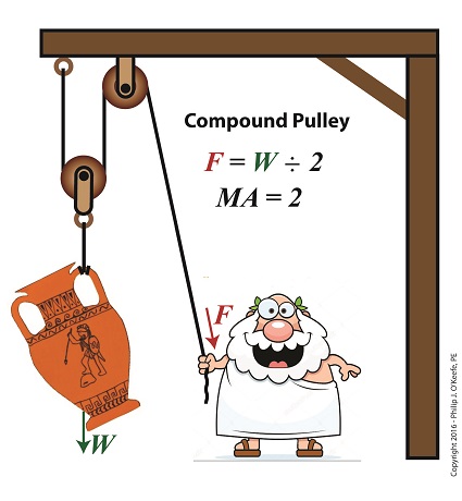
Last time we performed an engineering analysis of a compound pulley which resulted in an equation comparing the amount of true work effort, or work input, WI, required by machine or human to lift an object, in our case a toga’d man lifting an urn. Our analysis revealed that, in real world situations, work input does not equal work output, WO, due to the presence of friction. Today we’ll begin to numerically demonstrate their inequality by first solving for work output, and later work input.
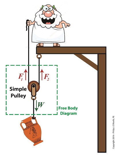
Comparing Work Input to Output in a Compound Pulley
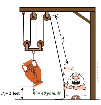
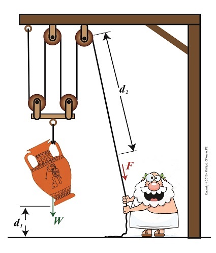
To solve for the work output of our compound pulley, we’ll use an equation provided previously that is in terms of the variables W and d1, WO = W × d1 (1) In our example Mr. Toga lifts an urn of weight, W, equal to 40 pounds to a height, or distance off the floor, d1, of 2 feet. Inserting these values into equation (1) we arrive at, WO = 40 pounds × 2 feet = 80 Ft-Lbs (2) where, Ft-Lbs is a unit of work which denotes pounds of force moving through feet of distance. Now that we’ve calculated the work output, we’ll turn our attention to the previously-derived equation for work input, shown in equation (3). Interrelating equations for WO and WI will enable us to solve for unknown variables, including the force, F, required to lift the urn and the length of rope, d2, extracted during lifting. Once F and d2 are known, we can solve for the additional force required to overcome friction, FF, then finally we’ll solve for WI. Once again, the equation we’ll be working with is, WI = (F × d2) + (FF × d2) (3) To calculate F, we’ll work the two terms present within parentheses separately, then use knowledge gained to further work our way towards a numerical comparison of work input and work output. We’ll do that next time. Copyright 2017 – Philip J. O’Keefe, PE Engineering Expert Witness Blog ____________________________________ |