Posts Tagged ‘work’
Wednesday, December 6th, 2017
|
Last time we developed an engineering formula to calculate the horsepower required to accelerate a flywheel by way of a reciprocating steam engine, which contributes to the storage of kinetic energy inside a flywheel. Today we’ll gain a clearer understanding of how this works when we take a look inside a reciprocating steam engine.
A Look Inside a Reciprocating Steam Engine
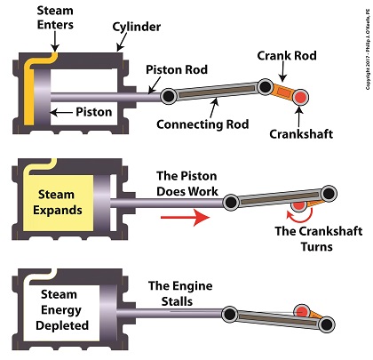
A reciprocating steam engine performs the work of transforming steam’s heat energy into the mechanical energy needed to move a piston contained within a cylinder. During a complete operating cycle this piston travels from one end of the cylinder to the other, then back again. This is made possible because during the first half of the cycle pressurized steam enters one end of the cylinder and expands inside it, forcing the piston to move.
This process inside the cylinder results in movement of a piston that’s attached to a piston rod, which in turn is connected to a crankshaft via a connecting rod and crank rod. The crankshaft is a device which converts the reciprocating linear motion of an engine’s piston into rotary motion and in so doing facilitates the powering of any externally mounted rotating machinery attached to it. So long as there’s ample steam to power the internal piston, over time, energy in the form of horsepower will be available to externally mounted devices. The energy in the steam decreases as the steam expands behind the moving piston. So, the engine’s horsepower, will decrease as the piston travels to the end of the cylinder. If the energy in the steam should become depleted, the reciprocating steam engine will stall. The engine will no longer be able to perform work.
Next time we’ll see how a crankshaft works when we take a look inside it.
opyright 2017 – Philip J. O’Keefe, PE
Engineering Expert Witness Blog
____________________________________ |
Tags: connecting rod, crank rod, crankshaft, energy, engineering, flywheel, kinetic energy, piston rod, power, reciprocating steam engine, work
Posted in Engineering and Science, Expert Witness, Forensic Engineering, Innovation and Intellectual Property, Personal Injury, Product Liability | Comments Off on A Look Inside a Reciprocating Steam Engine
Saturday, July 29th, 2017
|
Last time we determined the value for one of the key variables in the Euler-Eytelwein Formula known as the angle of wrap. To do so we worked with the relationship between the two tensions present in our example pulley-belt assembly, T1 and T2. Today we’ll use physics to solve for T2 and arrive at the Mechanical Power Formula, which enables us to compute the amount of power present in our pulley and belt assembly, a common engineering task.
To start things off let’s reintroduce the equation which defines the relationship between our two tensions, the Euler-Eytelwein Formula, with the value for e, Euler’s Number, and its accompanying coefficients, as determined from our last blog,
T1 = 2.38T2 (1)
Before we can calculate T1 we must calculate T2. But before we can do that we need to discuss the concept of power.
The Mechanical Power Formula in Pulley and Belt Assemblies
Generally speaking, power, P, is equal to work, W, performed per unit of time, t, and can be defined mathematically as,
P = W ÷ t (2)
Now let’s make equation (2) specific to our situation by converting terms into those which apply to a pulley and belt assembly. As we discussed in a past blog, work is equal to force, F, applied over a distance, d. Looking at things that way equation (2) becomes,
P = F × d ÷ t (3)
In equation (3) distance divided by time, or “d ÷ t,” equals velocity, V. Velocity is the distance traveled in a given time period, and this fact is directly applicable to our example, which happens to be measured in units of feet per second. Using these facts equation (3) becomes,
P = F × V (4)
Equation (4) contains variables that will enable us to determine the amount of mechanical power, P, being transmitted in our pulley and belt assembly.
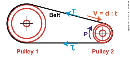
The force, F, is what does the work of transmitting mechanical power from the driving pulley, pulley 2, to the passive driven pulley, pulley1. The belt portion passing through pulley 1 is loose but then tightens as it moves through pulley 2. The force, F, is the difference between the belt’s tight side tension, T1, and loose side tension, T2. Which brings us to our next equation, put in terms of these two tensions,
P = (T1 – T2) × V (5)
Equation (5) is known as the Mechanical Power Formula in pulley and belt assemblies.
The variable V, is the velocity of the belt as it moves across the face of pulley 2, and it’s computed by yet another formula. We’ll pick up with that issue next time.
Copyright 2017 – Philip J. O’Keefe, PE
Engineering Expert Witness Blog
____________________________________ |
Tags: belt, distance divided by time, engineering, Euler-Eytelwein Formula, Euler's Number, force, loose side tension, mechanical power, mechanical power formula, power, power transmitted, pulley, tight side tension, velocity, work
Posted in Engineering and Science, Expert Witness, Forensic Engineering, Innovation and Intellectual Property, Personal Injury, Product Liability | Comments Off on The Mechanical Power Formula in Pulley and Belt Assemblies
Tuesday, February 28th, 2017
|
For some time now we’ve been analyzing the helpfulness of the engineering phenomena known as pulleys and we’ve learned that, yes, they can be very helpful, although they do have their limitations. One of those ever-present limitations is due to the inevitable presence of friction between moving parts. Like an unsummoned gremlin, friction will be standing by in any mechanical situation to put the wrench in the works. Today we’ll calculate just how much friction is present within the example compound pulley we’ve been working with.

So How Much Friction is Present in our Compound Pulley?
Last time we began our numerical demonstration of the inequality between a compound pulley’s work input, WI, and work output, WO, an inequality that’s due to friction in its wheels. We began things by examining a friction-free scenario and discovered that to lift an urn with a weight, W, of 40 pounds a distance, d1, of 2 feet above the ground, Mr. Toga exerts a personal effort/force, F, of 10 pounds to extract a length of rope, d2, of 8 feet.
In reality our compound pulley must contend with the effects of friction, so we know it will take more than 10 pounds of force to lift the urn, a resistance which we’ll notate FF. To determine this value we’ll attach a spring scale to Mr. Toga’s end of the rope and measure his actual lifting force, FActual, represented by the formula,
FActual = F + FF (1)
We find that FActual equals 12 pounds. Thus our equation becomes,
12 Lbs = 10 Lbs + FF (2)
which simplifies to,
2 Lbs = FF (3)
Now that we’ve determined values for all operating variables, we can solve for work input and then contrast our finding with work output,
WI = (F × d2) + (FF × d2) (4)
WI = (10 Lbs × 8 feet) + (2 Lbs × 8 feet) (5)
WI = 96 Ft-Lbs (6)
We previously calculated work output, WO to be 80 Ft-Lbs, so we’re now in a position to calculate the difference between work input and work output to be,
WI – WO = 16 Ft-Lbs (7)
It’s evident that the amount of work Mr. Toga puts into lifting his urn requires 16 more Foot-Pounds of work input effort than the amount of work output produced. This extra effort that’s required to overcome the pulley’s friction is the same as the work required to carry a weight of one pound a distance of 16 feet. We can thus conclude that work input does not equal work output in a compound pulley.
Next time we’ll take a look at a different use for pulleys beyond that of just lifting objects.
Copyright 2017 – Philip J. O’Keefe, PE
Engineering Expert Witness Blog
____________________________________ |
Tags: compound pulley, engineering, friction, pulley, work, work input, work output
Posted in Engineering and Science, Expert Witness, Forensic Engineering, Innovation and Intellectual Property, Personal Injury, Product Liability | Comments Off on So How Much Friction is Present in our Compound Pulley?
Wednesday, November 30th, 2016
|
We’ve been discussing the mechanical advantage that compound pulleys provide to humans during lifting operations and last time we hit upon the fact that there comes a point of diminished return, a reality that engineers must negotiate in their mechanical designs. Today we’ll discuss one of the undesirable tradeoffs that results in a diminished return within a compound pulley arrangement when we compute the length of rope the Grecian man we’ve been following must grapple in order to lift his urn. What we’ll discover is a situation of mechanical overkill – like using a steamroller to squash a bug.

Mechanical Overkill
Just how much rope does Mr. Toga need to extract from our working example compound pulley to lift his urn two feet above the ground? To find out we’ll need to revisit the fact that the compound pulley is a work input-output device.
As presented in a past blog, the equations for work input, WI, and work output, WO, we’ll be using are,
WI = F × d2
WO = W × d1
Now, ideally, in a compound pulley no friction exists in the wheels to impede the rope’s movement, and that will be our scenario today. Our next blog will deal with the more complex situation where friction is present. So for our example today, with no friction present, work input equals output…
WI = WO
… and this fact allows us to develop an equation in terms of the rope length/distance factors in our compound pulley assembly, represented by d1 and d2, …
F × d2 = W × d1
d2 ÷ d1 = W ÷ F
Now, from our last blog we know that W divided by F represents the mechanical advantage, MA, to Mr. Toga of using the compound pulley, which was found to be 16, equivalent to the sections of rope directly supporting the urn. We’ll set the distance factors up in relation to MA, and the equation becomes…
d2 ÷ d1 = MA
d2 = MA × d1
d2 = 16 × 2 feet = 32 feet
What we discover is that in order to raise the urn 2 feet, our Grecian friend must manipulate 32 feet of rope – which would only make sense if he were lifting something far heavier than a 40 pound urn.
In reality, WI does not equal WO, due to the inevitable presence of friction. Next time we’ll see how friction affects the mechanical advantage in our compound pulley.
Copyright 2016 – Philip J. O’Keefe, PE
Engineering Expert Witness Blog
____________________________________ |
Tags: compound pulley, engineer, force times distance, lift, mechanical advantage, mechanical design, pulley, rope length, work, work input, work output
Posted in Engineering and Science, Expert Witness, Forensic Engineering, Innovation and Intellectual Property, Personal Injury, Product Liability | Comments Off on Mechanical Overkill, an Undesirable Tradeoff in Compound Pulleys
Friday, November 18th, 2016
|
We’re all familiar with the phrase, “too much of a good thing.” As a professional engineer, I’ve often found this to be true. No matter the subject involved, there inevitably comes a point when undesirable tradeoffs occur. We’ll begin our look at this phenomenon in relation to compound pulleys today, and we’ll see how the pulley arrangement we’ve been working with encounters a rope length tradeoff. Today’s arrangement has a lot of pulleys lifting an urn a short distance.
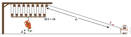
We’ll be working with two distance/length factors and observe what happens when the number of pulleys is increased. Last time we saw how the compound pulley is essentially a work input-output device, which makes use of distance factors. In our example below, the first distance/length factor, d1, pertains to the distance the urn is lifted above the ground. The second factor, d2, pertains to the length of rope Mr. Toga extracts from the pulley while actively lifting. It’s obvious that some tradeoff has occurred just by looking at the two lengths of rope in the image below as compared to last week. What we’ll see down the road is that this also affects mechanical advantage.
The compound pulley here consists of 16 pulleys, therefore it provides a mechanical advantage, MA, of 16. For a refresher on how MA is determined, see our preceding blog.
Rope Length Tradeoff in a Compound Pulley
With an MA of 16 and the urn’s weight, W, at 40 pounds, we compute the force, F, Mr. Toga must exert to actively lift the urn higher must be greater than,
F > W ÷ MA
F > 40 Lbs. ÷ 16
F > 2.5 Lbs.
Although the force required to lift the urn is a small fraction of the urn’s weight, Mr. Toga must work with a long and unwieldy length of rope. How long? We’ll find out next time when we’ll take a closer look at the relationship between d1 and d2.
Copyright 2016 – Philip J. O’Keefe, PE
Engineering Expert Witness Blog
____________________________________ |
Tags: compound pulley, effor, force, mechanical advantage, professional engineer, pulley, rope length, weight force, work
Posted in Courtroom Visual Aids, Engineering and Science, Forensic Engineering, Innovation and Intellectual Property, Personal Injury, Product Liability, Professional Malpractice | Comments Off on Rope Length Tradeoff in a Compound Pulley
Sunday, November 6th, 2016
|
In our last blog we saw how adding extra pulleys resulted in mechanical advantage being doubled, which translates to a 50% decreased lifting effort over a previous scenario. Pulleys are engineering marvels that make our lives easier. Theoretically, the more pulleys you add to a compound pulley arrangement, the greater the mechanical advantage — up to a point. Eventually you’d encounter undesirable tradeoffs. We’ll examine those tradeoffs, but before we do we’ll need to revisit the engineering principle of work and see how it applies to compound pulleys as a work input-output device.
Pulleys as a Work Input-Outut Device
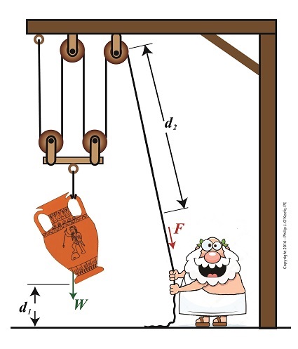
The compound pulley arrangement shown includes distance notations, d1 and d2. Their inclusion allows us to see it as a work input-output device. Work is input by Mr. Toga, we’ll call that WI, when he pulls his end of the rope using his bicep force, F. In response to his efforts, work is output by the compound pulley when the urn’s weight, W, is lifted off the ground against the pull of gravity. We’ll call that work output WO.
In a previous blog we defined work as a factor of force multiplied by distance. Using that notation, when Mr. Toga exerts a force F to pull the rope a distance d2 , his work input is expressed as,
WI = F × d2
When the compound pulley lifts the urn a distance d1 above the ground against gravity, its work output is expressed as,
WO = W × d1
Next time we’ll compare our pulley’s work input to output to develop a relationship between d1 and d2. This relationship will illustrate the first undesirable tradeoff of adding too many pulleys.
Copyright 2016 – Philip J. O’Keefe, PE
Engineering Expert Witness Blog
____________________________________ |
Tags: compound pulley, distance, engineering, engineering principle, force, mechanical advantage, pulley, weight, work, work input-output device, work of lifting
Posted in Engineering and Science, Expert Witness, Forensic Engineering, Innovation and Intellectual Property, Personal Injury, Product Liability | Comments Off on Pulleys as a Work Input-Outut Device
Monday, June 6th, 2016
|
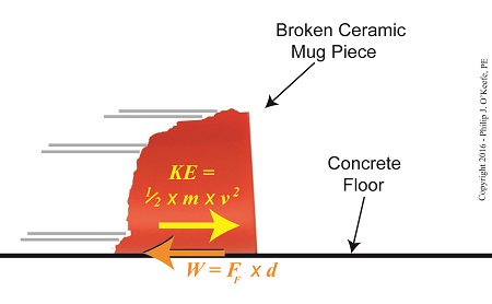
As an engineering expert, I often use the fact that formulas share a single common factor in order to set them equal to each other, which enables me to solve for a variable contained within one of them. Using this approach we’ll calculate the velocity, or speed, at which the broken bit of ceramic from the coffee mug we’ve been following slides across the floor until it’s finally brought to a stop by friction between it and the floor. We’ll do so by combining two equations which each solve for kinetic energy in their own way.
Last time we used this formula to calculate the kinetic energy, KE, contained within the piece,
KE = FF × d (1)
and we found that it stopped its movement across the floor when it had traveled a distance, d, of 2 meters.
We also solved for the frictional force, FF, which hampered its free travel, and found that quantity to be 0.35 kilogram-meters/second2. Thus the kinetic energy contained within that piece was calculated to be 0.70 kilogram-meters2/second2.
Now we’ll put a second equation into play. It, too, provides a way to solve for kinetic energy, but using different variables. It’s the version of the formula that contains the variable we seek to calculate, v, for velocity. If you’ll recall from a previous blog, that equation is,
KE = ½ × m × v2 (2)
Of the variables present in this formula, we know the mass, m, of the piece is equal to 0.09 kilograms. Knowing this quantity and the value derived for KE from formula (1), we’ll substitute known values into formula (2) and solve for v, the velocity, or traveling speed, of the piece at the beginning of its slide.

Combining Kinetic Energy Formulas to Calculate Velocity
The ceramic piece’s velocity is thus calculated to be,
KE = ½ × m × v2
0.70 kilogram-meters2/second2= ½ × (0.09 kilograms) × v2
now we’ll use algebra to rearrange things and isolate v to solve for it,
v2 = 2 × (0.70 kilogram-meters2/second2) ÷ (0.09 kilograms)
v = 3.94 meters/second =12.92 feet/second = 8.81 miles per hour
Our mug piece therefore began its slide across the floor at about the speed of an experienced jogger.

This ends our series on the interrelationship of energy and work. Next time we’ll begin a new topic, namely, how pulleys make the work of lifting objects and driving machines easier.
Copyright 2016 – Philip J. O’Keefe, PE
Engineering Expert Witness Blog
____________________________________ |
Tags: distance, energy, engineering expert, friction, frictional force, kinetic energy, mass, velocity, work
Posted in Engineering and Science, Expert Witness, Forensic Engineering, Innovation and Intellectual Property, Personal Injury, Product Liability | Comments Off on Combining Kinetic Energy Formulas to Calculate Velocity
Wednesday, May 25th, 2016
|
My activities as an engineering expert often involve creative problem solving of the sort we did in last week’s blog when we explored the interplay between work and kinetic energy. We used the Work-Energy Theorem to mathematically relate the kinetic energy in a piece of ceramic to the work performed by the friction that’s produced when it skids across a concrete floor. A new formula was derived which enables us to calculate the kinetic energy contained within the piece at the start of its slide by means of the work of friction. We’ll crunch numbers today to determine that quantity.
The formula we derived last time and that we’ll be working with today is,
 Calculating Kinetic Energy By Means of the Work of Friction
where, KE is the ceramic piece’s kinetic energy, FF is the frictional force opposing its movement across the floor, and d is the distance it travels before friction between it and the less than glass-smooth floor brings it to a stop.
The numbers we’ll need to work the equation have been derived in previous blogs. We calculated the frictional force, FF, acting against a ceramic piece weighing 0.09 kilograms to be 0.35 kilogram-meters/second2 and the measured distance, d, it travels across the floor to be equal to 2 meters. Plugging in these values, we derive the following working equation,
KE = 0.35 kilogram-meters/second2 × 2 meters
KE = 0.70 kilogram-meters2/second2
The kinetic energy contained within that broken bit of ceramic is just about what it takes to light a 1 watt flashlight bulb for almost one second!
Now that we’ve determined this quantity, other energy quantities can also be calculated, like the velocity of the ceramic piece when it began its slide. We’ll do that next time.
Copyright 2016 – Philip J. O’Keefe, PE
Engineering Expert Witness Blog
____________________________________ |
Tags: distance, electrical energy, energy, engineering expert, frictional force, kinetic energy, mass, velocity, Watt, work, work of friction, work-energy theorem
Posted in Engineering and Science, Expert Witness, Forensic Engineering, Innovation and Intellectual Property, Personal Injury, Product Liability | Comments Off on Calculating Kinetic Energy By Means of the Work of Friction
Thursday, May 12th, 2016
|
We’ve been discussing the different forms energy takes, delving deeply into de Coriolis’ claim that energy doesn’t ever die or disappear, it simply changes forms depending on the tasks it’s performing. Today we’ll combine mathematical formulas to derive an equation specific to our needs, an activity my work as an engineering expert frequently requires of me. Our task today is to find a means to calculate the amount of kinetic energy contained within a piece of ceramic skidding across a concrete floor. To do so we’ll combine the frictional force and Work-Energy Theorem formulas to observe the interplay between work and kinetic energy.
As we learned studying the math behind the Work-Energy Theorem, it takes work to slow a moving object. Work is present in our example due to the friction that’s created when the broken piece moves across the floor. The formula to calculate the amount of work being performed in this situation is written as,
W = FF ×d (1)
where, d is the distance the piece travels before it stops, and FF is the frictional force that stops it.
We established last time that our ceramic piece has a mass of 0.09 kilograms and the friction created between it and the floor was calculated to be 0.35 kilogram-meters/second2. We’ll use this information to calculate the amount of kinetic energy it contains. Here again is the kinetic energy formula, as presented previously,
KE = ½ × m × v2 (2)
where m represents the broken piece’s mass and v its velocity when it first begins to move across the floor.
The Interplay of Work and Kinetic Energy
The Work-Energy Theorem states that the work, W, required to stop the piece’s travel is equal to its kinetic energy, KE, while in motion. This relationship is expressed as,
KE = W (3)
Substituting terms from equation (1) into equation (3), we derive a formula that allows us to calculate the kinetic energy of our broken piece if we know the frictional force, FF, acting upon it which causes it to stop within a distance, d,
KE = FF × d
Next time we’ll use this newly derived formula, and the value we found for FF in our previous article, to crunch numbers and calculate the exact amount of kinetic energy contained with our ceramic piece.
Copyright 2016 – Philip J. O’Keefe, PE
Engineering Expert Witness Blog
____________________________________ |
Tags: distance, energy, engineering expert, frictional force, kinetic energy, mass, velocity, work, work-energy theorem
Posted in Engineering and Science, Expert Witness, Forensic Engineering, Innovation and Intellectual Property, Personal Injury, Product Liability | Comments Off on The Interplay of Work and Kinetic Energy
Monday, April 4th, 2016
|
Humans have been battling the force of friction since the first cave man built the wheel. Chances are his primitive tools produced a pretty crude wheel that first go-around and the wheel’s surfaces were anything but smooth, making its usefulness less than optimal. As an engineering expert, I encounter these same dynamics when designing modern devices. What held true for the cave man holds true for modern man, friction is often a counterproductive force which design engineers must work to minimize. Today we’ll learn about frictional force and see how it impacts our example broken coffee mug’s scattering pieces, and we’ll introduce the man behind friction’s discovery, Charles-Augustin de Coulomb.
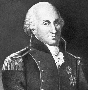
Charles-Augustin de Coulomb
Last time we learned that the work required to shatter our mug was transformed into the kinetic energy which propelled its broken pieces across a rough concrete floor. The broken pieces’ energetic transformation will continue as the propelling force of kinetic energy held within them is transmuted back into the work that will bring each one to an eventual stop a distance from the point of impact. This last source of work is due to the force of friction.
In 1785 Charles-Augustin de Coulomb, a French physicist, discovered that friction results when two surfaces make contact with one another, and that friction is of two types, static or dynamic. Although Leonardo Da Vinci had studied friction hundreds of years before him, it is Coulomb who is attributed with doing the ground work that later enabled scientists to derive the formula to calculate the effects of friction. Our example scenario illustrates dynamic friction, that is to say, the friction is caused by one of the surfaces being in motion, namely the mug’s ceramic pieces which skid across a stationary concrete floor.
While in motion, each of the mug’s broken pieces has its own unique velocity and mass and therefore a unique amount of kinetic energy. The weight of each piece acts as a vertical force pushing the piece down “into” the floor, this due to the influence of Earth’s gravitational pull, that is, the force of gravity.
Friction is created by a combination of factors, including the ceramic pieces’ weights and the surface roughness of both the pieces themselves and the concrete floor they skid across. At first glance the floor and ceramic mug’s surfaces may appear slippery smooth, but when viewed under magnification it’s a whole different story.
Next time we’ll examine the situation under magnification and we’ll introduce the formula used to calculate friction along with a rather odd sounding variable, mu.
Copyright 2016 – Philip J. O’Keefe, PE
Engineering Expert Witness Blog
____________________________________ |
Tags: calculating frictional force, Charles-Augustin de Coulomb, contacting surfaces, dynamic friction, energetic transformation, engineering expert witness, friction, frictional force, kinetic energy, Leonardo Da Vinci, roughness, static friction, work
Posted in Engineering and Science, Expert Witness, Forensic Engineering, Innovation and Intellectual Property, Personal Injury, Product Liability | Comments Off on Coulomb’s Frictional Force


