|
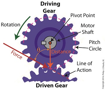
We’ve been discussing torque and how it enables more power to be available to applications such as loosening tight nuts with a wrench. Now we’ll see how those same principles apply to another application, a simple gear train. To review, the torque formula is, Torque = Distance × Force × sin(ϴ) where, Distance and Force are vector magnitudes and ϴ is the angle formed between them. Referring to the gear train illustration above, we see that Force and Distance vectors are present, just as they had been in our previous wrench/nut example. But instead of torque being created by way of force that’s applied to a wrench, things are reversed, and it’s the torque that creates the force. You see, in the wrench/nut example, the force applied to the wrench handle created torque on the nut. In our present gear train example, the torque applied to the motor shaft is created by an electric motor exerting pressure upon the motor shaft, which in turn exerts a force upon the driving gear teeth. The driving gear is also attached to this shaft, so torque causes the driving gear to rotate along with the motor. This rotation results in a force being exerted at the point where the teeth of the driving gear mesh with the teeth of the driven gear. In other words, in the wrench/nut example force created torque, while in the present example torque creates a force. The gear train has a pivot point, as there was in our wrench/nut example, but this time it’s located at the center of the motor shaft rather than at the center of a nut. The pivot point in both examples is where the action takes place. The motor’s shaft and driving gear rotate around it, just as the wrench jaws and handle rotated around the nut’s pivot point. In both examples, the Distance vectors extend out from the pivot points to meet up with the Force vector’s path. In the gear train example, this Force vector path is called a line of action, as introduced earlier in this blog series. This line of action passes through to the point where the driving and driven gear teeth mesh. The force acting upon that point causes the gears in the gear train to rotate, and as they turn mechanical energy is transferred from the motor to whatever machinery component is attached to the shaft of the driven gear. The powered component will then be able to perform useful work such as cutting lumber, mixing frosting for a cake, drilling holes in steel, or propelling vehicles. You will note that there is an angle ϴ which exists between the Distance and Force vectors. Since we have a pivot point, a Force vector, a Distance vector, and an angle ϴ, we are able to apply the torque formula to gear trains exactly as we did in our wrench/nut example. We can then use that formula to calculate how torque is transmitted between gears in the train. Next time we’ll examine the distance and force vectors in a simple gear train. _______________________________________ |
Tags: distance vector, driven gear, driving gear, engineering expert witness, force, force vector, forensic engineer, gear expert witness, gear teeth, gear teeth mesh, gear train, line of action, machine design, machinery, mechanical design, mechanical energy, mechanical engineer, nut, pivot point, torque, torque formula, wrench


