Posts Tagged ‘mechanical design’
Tuesday, December 13th, 2016
|
The presence of friction in mechanical designs is as guaranteed as conflict in a good movie, and engineers inevitably must deal with the conflicts friction produces within their mechanical designs. But unlike a good movie, where conflict presents a positive, engaging force, friction’s presence in pulleys results only in impediment, wasting energy and reducing mechanical advantage. We’ll investigate the math behind this phenomenon in today’s blog.
Friction Reduces Pulleys’ Mechanical Advantage
A few blogs back we performed a work input-output analysis of an idealized situation in which no friction is present in a compound pulley. The analysis yielded this equation for mechanical advantage,
MA = d2 ÷ d1 (1)
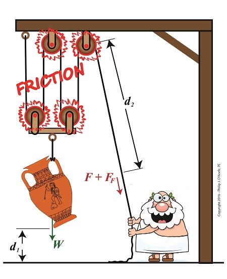
where d2 is the is the length of rope Mr. Toga extracts from the pulley in order to lift his urn a distance d1 above the ground. Engineers refer to this idealized frictionless scenario as an ideal mechanical advantage, IMA, so equation (1) becomes,
IMA = d2 ÷ d1 (2)
We also learned that in the idealized situation mechanical advantage is the ratio of the urn’s weight force, W, to the force exerted by Mr. Toga, F, as shown in the following equation. See our past blog for a refresher on how this ratio is developed.
IMA = W ÷ F (3)
In reality, friction exists between a pulley’s moving parts, namely, its wheels and the rope threaded through them. In fact, the more pulleys we add, the more friction increases.
The actual amount of lifting force required to lift an object is a combination of FF , the friction-filled force, and F, the idealized friction-free force. The result is FActual as shown here,
FActual = F + FF (4)
The real world scenario in which friction is present is known within the engineering profession as actual mechanical advantage, AMA, which is equal to,
AMA = W ÷ FActual (5)
To see how AMA is affected by friction force FF, let’s substitute equation (4) into equation (5),
AMA = W ÷ (F + FF) (6)
With the presence of FF in equation (6), W gets divided by the sum of F and FF . This results in a smaller number than IMA, which was computed in equation (3). In other words, friction reduces the actual mechanical advantage of the compound pulley.
Next time we’ll see how the presence of FF translates into lost work effort in the compound pulley, thus creating an inequality between the work input, WI and work output WO.
Copyright 2016 – Philip J. O’Keefe, PE
Engineering Expert Witness Blog
____________________________________ |
Tags: actual mechanical advantage, AMA, compound pulley, engineering, friction, friction force, ideal mechanical advantage, IMA, mechanical advantage, mechanical design, pulley, pulley friction, pulley work input, pulley work output, weight force
Posted in Engineering and Science, Expert Witness, Forensic Engineering, Innovation and Intellectual Property, Personal Injury, Product Liability | Comments Off on Friction Reduces Pulleys’ Mechanical Advantage
Wednesday, November 30th, 2016
|
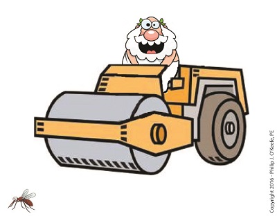
We’ve been discussing the mechanical advantage that compound pulleys provide to humans during lifting operations and last time we hit upon the fact that there comes a point of diminished return, a reality that engineers must negotiate in their mechanical designs. Today we’ll discuss one of the undesirable tradeoffs that results in a diminished return within a compound pulley arrangement when we compute the length of rope the Grecian man we’ve been following must grapple in order to lift his urn. What we’ll discover is a situation of mechanical overkill – like using a steamroller to squash a bug.
Mechanical Overkill
Just how much rope does Mr. Toga need to extract from our working example compound pulley to lift his urn two feet above the ground? To find out we’ll need to revisit the fact that the compound pulley is a work input-output device.
As presented in a past blog, the equations for work input, WI, and work output, WO, we’ll be using are,
WI = F × d2
WO = W × d1
Now, ideally, in a compound pulley no friction exists in the wheels to impede the rope’s movement, and that will be our scenario today. Our next blog will deal with the more complex situation where friction is present. So for our example today, with no friction present, work input equals output…
WI = WO
… and this fact allows us to develop an equation in terms of the rope length/distance factors in our compound pulley assembly, represented by d1 and d2, …
F × d2 = W × d1
d2 ÷ d1 = W ÷ F
Now, from our last blog we know that W divided by F represents the mechanical advantage, MA, to Mr. Toga of using the compound pulley, which was found to be 16, equivalent to the sections of rope directly supporting the urn. We’ll set the distance factors up in relation to MA, and the equation becomes…
d2 ÷ d1 = MA
d2 = MA × d1
d2 = 16 × 2 feet = 32 feet
What we discover is that in order to raise the urn 2 feet, our Grecian friend must manipulate 32 feet of rope – which would only make sense if he were lifting something far heavier than a 40 pound urn.
In reality, WI does not equal WO, due to the inevitable presence of friction. Next time we’ll see how friction affects the mechanical advantage in our compound pulley.
Copyright 2016 – Philip J. O’Keefe, PE
Engineering Expert Witness Blog
____________________________________ |
Tags: compound pulley, engineer, force times distance, lift, mechanical advantage, mechanical design, pulley, rope length, work, work input, work output
Posted in Engineering and Science, Expert Witness, Forensic Engineering, Innovation and Intellectual Property, Personal Injury, Product Liability | Comments Off on Mechanical Overkill, an Undesirable Tradeoff in Compound Pulleys
Tuesday, June 28th, 2016
|
Pulleys are simple devices with many uses, and as an engineering expert, I’ve often incorporated them into mechanical designs. They’re used in machinery to transmit mechanical power from electric motors and engines to devices like blowers and pumps. Another common usage for pulleys is to aid in lifting. There are two types of pulleys for this purpose, simple or compound. We’ll start our discussion off by looking at the simple type today.
The simple pulley may have been an advanced application of the wheel. It consists of a furrowed wheel on a shaft with some device for pulling threaded through it. The pulley wheel supports and guides the movement of a rope, cable, or other pulling device around its circumference. The pulling device runs between a pull-ee and pull-er, that is, the object to be moved and the source of pulling power, with the pulley itself situated somewhere between them.
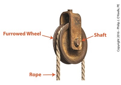
Simple Pulley
Pulleys are believed to have first been used by the Greeks as early as the 9th Century BC. We’ll look into how they put them to use next time.
Copyright 2016 – Philip J. O’Keefe, PE
Engineering Expert Witness Blog
____________________________________ |
Tags: belt, blower, cable, compound pulley, electric motors, engineering expert, engines, mechanical design, pulley, pumps, simple pulleys, transmit mechanical power
Posted in Engineering and Science, Expert Witness, Forensic Engineering, Innovation and Intellectual Property, Personal Injury, Product Liability | Comments Off on Simple Pulleys
Tuesday, April 29th, 2014
|
We’ve been discussing torque and how it enables more power to be available to applications such as loosening tight nuts with a wrench. Now we’ll see how those same principles apply to another application, a simple gear train.
To review, the torque formula is,
Torque = Distance × Force × sin(ϴ)
where, Distance and Force are vector magnitudes and ϴ is the angle formed between them.

Referring to the gear train illustration above, we see that Force and Distance vectors are present, just as they had been in our previous wrench/nut example. But instead of torque being created by way of force that’s applied to a wrench, things are reversed, and it’s the torque that creates the force.
You see, in the wrench/nut example, the force applied to the wrench handle created torque on the nut. In our present gear train example, the torque applied to the motor shaft is created by an electric motor exerting pressure upon the motor shaft, which in turn exerts a force upon the driving gear teeth. The driving gear is also attached to this shaft, so torque causes the driving gear to rotate along with the motor. This rotation results in a force being exerted at the point where the teeth of the driving gear mesh with the teeth of the driven gear. In other words, in the wrench/nut example force created torque, while in the present example torque creates a force.
The gear train has a pivot point, as there was in our wrench/nut example, but this time it’s located at the center of the motor shaft rather than at the center of a nut. The pivot point in both examples is where the action takes place. The motor’s shaft and driving gear rotate around it, just as the wrench jaws and handle rotated around the nut’s pivot point.
In both examples, the Distance vectors extend out from the pivot points to meet up with the Force vector’s path. In the gear train example, this Force vector path is called a line of action, as introduced earlier in this blog series. This line of action passes through to the point where the driving and driven gear teeth mesh. The force acting upon that point causes the gears in the gear train to rotate, and as they turn mechanical energy is transferred from the motor to whatever machinery component is attached to the shaft of the driven gear. The powered component will then be able to perform useful work such as cutting lumber, mixing frosting for a cake, drilling holes in steel, or propelling vehicles.
You will note that there is an angle ϴ which exists between the Distance and Force vectors. Since we have a pivot point, a Force vector, a Distance vector, and an angle ϴ, we are able to apply the torque formula to gear trains exactly as we did in our wrench/nut example. We can then use that formula to calculate how torque is transmitted between gears in the train.
Next time we’ll examine the distance and force vectors in a simple gear train.
_______________________________________
|
Tags: distance vector, driven gear, driving gear, engineering expert witness, force, force vector, forensic engineer, gear expert witness, gear teeth, gear teeth mesh, gear train, line of action, machine design, machinery, mechanical design, mechanical energy, mechanical engineer, nut, pivot point, torque, torque formula, wrench
Posted in Engineering and Science, Expert Witness, Forensic Engineering, Innovation and Intellectual Property, Personal Injury, Product Liability | Comments Off on Torque and Force
Sunday, March 31st, 2013
|
While pursuing my engineering degree my professors provided me with a thorough understanding of mechanical and electrical design and instruction on how to build prototypes for testing. As far as technical skills were concerned, I was well equipped to turn my ideas into real inventions. Unfortunately, my engineering school, like most others, never went beyond these technical aspects of inventing. For example, we never discussed the business and legal aspects of manufacturing and selling an invention.
The fact is, most first time inventors have little or no understanding of how to go about obtaining a patent to prevent others from copying and profiting from their inventions. They also tend to take a haphazard approach to inventing, neglecting important issues such as whether a market for their invention exists, or whether they will face competition already in place. A lot of time and money can be spent developing an invention, only to discover that it had already been patented by someone else. They do all the up-front work, blissfully unaware of the repercussions of negative possibilities, like getting sued by any existing patent holder, suits which are among the most expensive to defend.
For most individuals the patent process is a hotbed of mysteries and misconceptions. Let’s start unraveling them by first gaining a basic understanding of what a patent is.
In short, a patent grants you a legal right, much like other legal rights you may be more familiar with. For example, if you own property, say a car or piece of real estate, you’re provided with a legal document known as a title. This title defines your legal right to own that property.
Similar to a title, a patent grants you the legal right to own intellectual property, or IP, as its inventor. IP is a term used in the business and legal arenas to refer to creations of the inventor’s mind. Once patented, these creations become the property of the inventor, and they have commercial value. This value is derived from the fact that the patent can be used to exclude others from producing the invention and profiting from it. The IP rights can also be sold or licensed to others for a profit.
IP can encompass subjects as diverse as machinery, articles of manufacture, compositions of matter, and many diverse processes, all of which we’ll look into during the course of this blog series.
___________________________________________

|
Tags: articles of manufacture, compositions of matter, developing an invention, electrical design, engineering expert witness, intellectual property, inventions, inventor, IP, machinery, manufacturing, mechanical design, patent, patent holder, processes, prototypes
Posted in Engineering and Science, Expert Witness, Innovation and Intellectual Property | Comments Off on Patents, Defined
Sunday, May 13th, 2012
|
When I’m under a lot of stress I sometimes have the nervous habit of grabbing a paper clip, straightening out the bends, then repetitively bending it back and forth. Eventually the wire reaches a point where it just breaks apart.
My paper clip broke due to metal fatigue. Metal parts are said to become fatigued when they’re subjected to forces of a repetitive nature such as occur due to twisting and bending. The metal cracks, then eventually breaks due to the stress.
So what’s happening when metal becomes fatigued? Figure 1 shows the simplified atomic structure of a sample metal.

Figure 1
When the metal is deformed, such as during bending, its rows of atoms are forced to move with respect to each other as shown in Figure 2.

Figure 2
The movement of rows of atoms leads to an alteration in structure, breaking bonds between atoms. This results in small cracks forming along the metal’s surface, cracks which eventually migrate deeper inside the metal with each subsequent bend. With time the metal will become so compromised by the cracks that breakage occurs.
Metal fatigue can occur in centrifugal clutch mechanisms as well. Power tools such as grass trimmers typically operate between idle and working speeds many times during a day’s usage. As we learned in previous articles, when the engine runs at idle speed, the springs in the centrifugal clutch mechanism stay retracted. As the engine speeds up, the centrifugal force acting on the clutch shoes extends the springs. Successive extensions and retractions cause the metal in the springs to bend, and over time they, like my paper clip, will become fatigued and metal springs will break.
Next time we’ll continue talking about centrifugal clutch failures and learn how the springs of a clutch mechanism can fail without its metal being brought to the breaking point.
____________________________________________
|
Tags: atomic bonds, atomic structure, bending force, centrifugal clutch, clutch boss, clutch failure, clutch mechanism, clutch shoe, clutches, crack formation, engineering expert witness, forensic engineer, fracture, gasoline engine, grass trimmer, mechanical design, metal atoms, metal cracks, metal fatigue, metal parts, power tool, repetitive bending, springs, stress
Posted in Engineering and Science, Expert Witness, Forensic Engineering, Innovation and Intellectual Property, Personal Injury, Product Liability, Professional Malpractice | Comments Off on Mechanical Power Transmission – The Centrifugal Clutch and Metal Fatigue


