|
Last time we developed torque equations for the driving and driven gears within a simple gear train. They are, T1 = D1 × F T2 = D2 × F where, T1 and T2 are the driving and driven gear torques, D1 and D2 are the driving and driven gear pitch radii, and F is the resultant Force vector, the common factor between the two equations. Now we’ll combine these two equations relative to F to arrive at a single equation which equates the torques and pitch circle radii of the driving and driven gears in the gear train. This type of computation is commonly used to design gear trains to ensure they perform at a given level. As a first step we’ll use algebra to rearrange terms and place the two equations equal to F. First we’ll do it for the driving gear, dividing both sides of the equation by the pitch circle radius, D1. T1 ÷ D1 = D1 ÷ D1 × F T1 ÷ D1= 1 × F F = T1 ÷ D1 In a similar fashion, we’ll do it for the driven gear by dividing both sides of the equation by the pitch circle radius, D2. T2 = D2 × F → F = T2 ÷ D2 Since F is the common term between the two equations, we can set them up as equal to each other, F = T1 ÷ D1 = T2 ÷ D2 which means that, T1 ÷ D1 = T2 ÷ D2 Next time we’ll see how to use this equation to manipulate our gear train so that it acts as a torque converter by increasing T2 with respect to T1 and the ratio of D1 to D2, thus providing a mechanical advantage to the electric motor the gear train is attached to. _______________________________________ |
Posts Tagged ‘machine design’
Equating Torques and Pitch Circle Radii Within a Gear Train
Thursday, May 29th, 2014Torque and Force
Tuesday, April 29th, 2014|
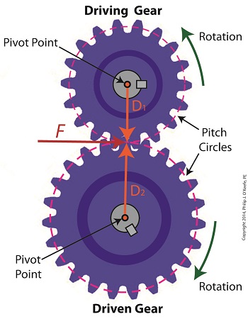
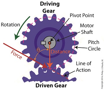
We’ve been discussing torque and how it enables more power to be available to applications such as loosening tight nuts with a wrench. Now we’ll see how those same principles apply to another application, a simple gear train. To review, the torque formula is, Torque = Distance × Force × sin(ϴ) where, Distance and Force are vector magnitudes and ϴ is the angle formed between them. Referring to the gear train illustration above, we see that Force and Distance vectors are present, just as they had been in our previous wrench/nut example. But instead of torque being created by way of force that’s applied to a wrench, things are reversed, and it’s the torque that creates the force. You see, in the wrench/nut example, the force applied to the wrench handle created torque on the nut. In our present gear train example, the torque applied to the motor shaft is created by an electric motor exerting pressure upon the motor shaft, which in turn exerts a force upon the driving gear teeth. The driving gear is also attached to this shaft, so torque causes the driving gear to rotate along with the motor. This rotation results in a force being exerted at the point where the teeth of the driving gear mesh with the teeth of the driven gear. In other words, in the wrench/nut example force created torque, while in the present example torque creates a force. The gear train has a pivot point, as there was in our wrench/nut example, but this time it’s located at the center of the motor shaft rather than at the center of a nut. The pivot point in both examples is where the action takes place. The motor’s shaft and driving gear rotate around it, just as the wrench jaws and handle rotated around the nut’s pivot point. In both examples, the Distance vectors extend out from the pivot points to meet up with the Force vector’s path. In the gear train example, this Force vector path is called a line of action, as introduced earlier in this blog series. This line of action passes through to the point where the driving and driven gear teeth mesh. The force acting upon that point causes the gears in the gear train to rotate, and as they turn mechanical energy is transferred from the motor to whatever machinery component is attached to the shaft of the driven gear. The powered component will then be able to perform useful work such as cutting lumber, mixing frosting for a cake, drilling holes in steel, or propelling vehicles. You will note that there is an angle ϴ which exists between the Distance and Force vectors. Since we have a pivot point, a Force vector, a Distance vector, and an angle ϴ, we are able to apply the torque formula to gear trains exactly as we did in our wrench/nut example. We can then use that formula to calculate how torque is transmitted between gears in the train. Next time we’ll examine the distance and force vectors in a simple gear train. _______________________________________ |
Determining Patent Eligibility – Part 4, Machines of a Different Kind
Sunday, April 28th, 2013|
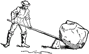
During 6th grade science we had a chapter on Simple Machines, and my textbook listed a common lever as an example, the sort that can be used to make work easier. Its illustration showed a stick perched atop a triangular shaped stone, appearing very much like a teeter-totter in the playground. A man was pushing down on one end of the stick to move a large boulder with the other end. Staring at it I thought to myself, “That doesn’t look like a machine to me. Where are its gears?” That day I learned about more than just levers, I learned to expect the unexpected when it comes to machines. Last time we learned that under patent law the machine referred to in federal statute 35 USC § 101 includes any physical device consisting of two or more parts which dynamically interact with each other. We looked at how a purely mechanical machine, such as a diesel engine, has moving parts that are mechanically linked to dynamically interact when the engine runs. Now, lets move on to less obvious examples of what constitutes a machine. Would you expect a modern electronic memory stick to be a machine? Probably not. But, under patent law it is. It’s an electronic device, and as such it’s made up of multiple parts, including integrated circuit chips, resistors, diodes, and capacitors, all of which are soldered to a printed circuit board where they interact with one another. They do so electrically, through changing current flow, rather than through physical movement of parts as in our diesel engine. A transformer is an example of another type of machine. An electrical machine. Its fixed parts, including wire coils and steel cores, interact dynamically both electrically and magnetically in order to change voltage and current flow. Electromechanical, the most complex of all machine types, includes the kitchen appliances in your home. They consist of both fixed and moving parts, along with all the dynamic interactions of mechanical, electronic, and electrical machines. Next time we’ll continue our discussion on the second hurtle presented by 35 USC § 101, where we’ll discuss what is meant by article of manufacture. ___________________________________________ |
Food Manufacturing Challenges
Sunday, September 18th, 2011| Some people just have a knack in the kitchen, and my wife is among them. She transforms raw ingredients into the most amazing culinary delights, almost like she’s waving a magic wand. The finished products are works of art, hand crafted with tender loving care, and lucky me, I get to feast on them regularly!
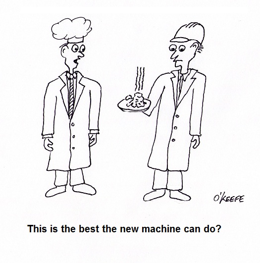
During the course of my engineering career I’ve been employed within many industries, and at one point I made the decision to leave the electric utility industry and enter into the world of food manufacturing. I accepted the position of Plant Engineer with a wholesale manufacturer of baking ingredients and frozen pastry products. My main responsibility was the design of food manufacturing equipment and their production lines. What I had expected to be a relatively straightforward process soon proved to be more challenging. I was no longer working with hard metal as my raw material, that is, gears, nuts, and bolts, but a whole new arena of things described by adjectives such as gooey and pastey. Engineers don’t typically create food products, and let’s face it, you probably wouldn’t want to eat anything that I cooked anyway! But an engineer working within a food manufacturing plant must act as a liaison between the worlds of engineering design and the culinary arts. Now food manufacturers typically hire professional chefs to develop new products in their research and development (R&D) kitchens. Like my wife, they’re well qualified to produce wonderful hand-made culinary delights. The sticky part comes in when their small batch recipes and preparation techniques don’t translate smoothly to the world of mass production. When it comes to handling food, human fingers are far superior to metal machinery, and raw ingredients behave differently for each. Herein lies much of the challenge for design engineers within the food industry. How do you design equipment and production lines to make huge quantities of food that look and taste as good as the prototype products made by hand in the R&D kitchen? Next week we’ll find out. ____________________________________________ |
Machine Design in Mechanical Engineering
Sunday, March 21st, 2010|
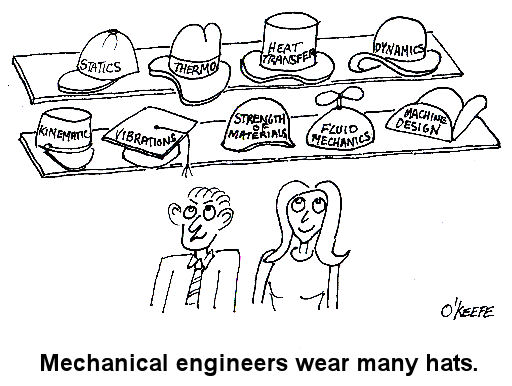
Last week we wrapped up our discussion of vibration analysis. It’s been a long time coming, but this week we’ll conclude our series on the many aspects of mechanical engineering by discussing machine design. If you’ve been with us since the beginning of the series and you’re not a mechanical engineer, I’d venture to say you’re now impressed with the wide scope of issues with which mechanical engineering is concerned. In our preceding discussions we examined some basic concepts behind statics, dynamics, kinematics, strengths of materials, material science, thermodynamics, heat transfer, fluid mechanics, and vibrations. This is the foundation of mechanical engineering know-how. But when we consider machine design as a whole, we often have to keep in mind the old cliché, “Why reinvent the wheel?” I say this because engineers have been designing machines and mechanical systems for hundreds of years. Over this time, their design accomplishments have been collected, standardized, and tabulated in engineering handbooks and product catalogs to make things easier for future generations and to eliminate redundancy of work effort. Put another way, why design nuts, bolts, pumps, heat exchangers, motors, gears, pulleys, and drive belts for a new machine when someone already designed them for similar applications in the past and they are readily available for quick purchase from suppliers? For example, suppose you had to design a machine that will be driven by an electric motor using sprockets and a roller chain. This is the same method that your bicycle employs to transfer foot power applied to the pedals back to the rear wheel, which gets you rolling. So, how do you come up with a chain that will do the job without breaking? To incorporate a sprocket and roller chain drive system into your machine design, you must first determine how much horsepower you will need to run the machine, the speed at which it must operate, and the conditions under which it will operate. You can use this information to design a chain from scratch, then test it to see if it works, then have it custom manufactured. Translation: Lots of time, effort and money expended. Or, you could get a hold of a book that’s been around since 1914, Machinery’s Handbook. This is considered by many to be one of the best mechanical engineering reference handbooks of all time. It contains tables of information that can be used to select standard, commercially available roller chains based on both horsepower and speed requirements. It also has lots of other engineering-specific information on various other machine components. Based on our example above, I think you can conclude that the fastest, most economical route to take to construction of our mechanism is to use as many standardized, commercially available components as possible. Knowing where to find information on these components and how to use them is very important to the success of your design, and this is precisely the information that you would have picked up during your final year of study towards earning a Bachelor’s Degree in Mechanical Engineering. As a student, you would have been required to take at least a few machine design courses. Well, that’s it for our series on understanding the basics of mechanical engineering. I hope you enjoyed it and it helped you to better understand the fundamentals of what mechanical engineering is all about. _________________________________________________________________
|
