Archive for August, 2016

The Compound Pulley

Saturday, August 13th, 2016

    Sometimes one of something just isn’t enough, like one potato chip, one glass of wine… And when it comes to lifting massive objects one simple pulley isn’t going to be enough to get the job done.   Even the improved simple pulley, which we introduced last week, is often not enough, a situation which I’ve run across in my career as an engineering expert.   To get past the limitations of the simple pulley and improved simple pulley, ancient Greeks went on to devise the compound pulley, which we’ll introduce today.
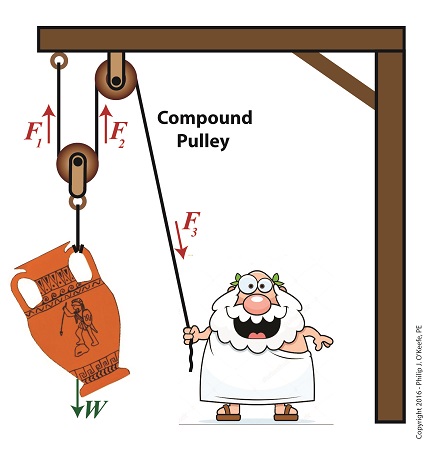
The Compound Pulley

The Compound Pulley


    A compound pulley, such as the one shown here, consists of two or more simple pulleys. In the compound pulley system, a combination of fixed and moveable simple pulleys are used to lift objects.   The scenario shown in our illustration features a compound pulley consisting of two simple pulleys, one is stationary and affixed to a beam, the other hangs freely in space, riding on the rope connecting them.   One end of the rope is held by Mr. Toga, the other end is affixed to the beam.   In fact, all compound pulleys require that at least one simple pulley be affixed to a stationary structure, and at least one other simple pulley must be free to move in space.

    When our toga clad friend pulls his end of the rope he exerts a force, F3, via the pulley affixed to the beam.   This force transmits on to the pulley attached to the urn, which results in lifting the urn off the ground.

    Next week we’ll calculate the force on Mr. Toga’s end, F3, as well as the other forces at play, F1 and F2.

Copyright 2016 – Philip J. O’Keefe, PE

Engineering Expert Witness Blog

____________________________________


The Math Behind the Improved Simple Pulley

Tuesday, August 2nd, 2016

    Last time we introduced the free body diagram, applied it to a simple pulley, and discovered that in so doing lifting objects required 50% less effort.   As an engineering expert, I’ve sometimes put this improved version of a simple pulley to work for me in designs.   We’ll do the math behind the improvement today.

    Here again is the free body diagram showing the improved simple pulley as introduced last week.

The Improved Simple Pulley

The Math Behind the Improved Simple Pulley

     The illustration shows the three forces, F1, F2, and W, acting upon the simple pulley within the highlighted free body diagram.   Forces F1 and F2 are exerted from above and act in opposition to the downward pull of gravity, represented by the weight of the urn, W.   Forces F1 and Fare produced by that which holds onto either end of the rope that’s threaded through the pulley.   In our case those forces are supplied by a man in a toga and a beam.   By engineering convention, these upward forces, F1 and F2, are considered positive, while the downward force, W, is negative.

    In the arrangement shown in our illustration, the pulley’s rope ends equally support the urn’s weight, as demonstrated by the fact that the urn remains stationary in space, neither moving up nor down.   In other words, forces F1 and F2 are equal.

    Now, according to the basic rule of free body diagrams, the three forces F1, F2, and W must add up to zero in order for the pulley to remain stationary.   Put another way, if the pulley isn’t moving up or down, the positive forces F1 and F2 are balancing the negative force presented by the urn’s weight, W.   Mathematically this looks like,

F1 + F2 – W = 0

or, by rearranging terms,

F1 + F2 = W

We know that F1 equals F2, so we can substitute F1 for F2 in the preceding equation to arrive at,

F1 + F1 = W

or,

2 × F1 = W

Using algebra to divide both sides of the equation by 2, we get:

F1 = W ÷ 2

Therefore,

F1 = F2 = W ÷ 2

    If the sum of the forces in a free body diagram do not equal zero, then the suspended object will move in space.   In our situation the urn moves up if our toga-clad friend pulls on his end of the rope, and it moves down if Mr. Toga reduces his grip and allows the rope to slide through his hand under the influence of gravity.

    The net real world benefit to our Grecian friend is that the urn’s 20-pound weight is divided equally between him and the beam.   He need only apply a force of 10 pounds to keep the urn suspended.

    Next time we’ll see how the improved simple pulley we’ve discussed today led to the development of the compound pulley, which enabled heavier objects to be lifted.

Copyright 2016 – Philip J. O’Keefe, PE

Engineering Expert Witness Blog

____________________________________