| Last week our kitchen ceiling fan and light combo decided to stop working. We don’t like eating in the dark, so I was compelled to do some immediate troubleshooting. As an engineer with training in the workings of electricity I have a great respect for it. I’m well aware of potential hazards, and I took a necessary precaution before taking things apart and disconnecting wires. I made the long haul down the stairs to the basement, opened the circuit breaker in the electrical panel, and disabled the flow of electricity to the kitchen. My fears of potential electrocution having been eliminated, my only remaining fear was of tumbling off the ladder while servicing the fan.
Just as I took the precaution to disconnect the power supply before performing electrical maintenance in my home, workers in industrial settings must do the same, and a chief player in those scenarios is the motor overload relay discussed last week. It automatically shuts down electric motors when they become overheated. Let’s revisit that example now.
Figure 1
Our diagram in Figure 1 shows electric current flowing through the circuit by way of the red path. Even if this line were shut down, current would continue to flow along the path, because there is no means to disconnect the entire control system from the hot and neutral lines supplying power to it, that is, it is missing disconnect switches. Electric current will continue to pose a threat to workers were they to attempt a repair to the system. Now let’s see how we can eliminate potential hazards on the line.
Figure 2
In Figure 2 there is an obvious absence of the color red, indicating the lack of current within the system. We accomplished this with the addition of disconnect switches capable of isolating the motor control circuitry, thereby cutting off the hot and neutral lines of the electrical power supply and along with it the unencumbered flow of electricity. These switches are basically the same as those seen in earlier diagrams in our series on industrial controls, the difference here is that the two switches are tied together by an insulated mechanical link. This link causes them to open and close at the same time. The switches are opened and closed manually via a handle. When the disconnect switches are both open electricity can’t flow and nothing can operate. Under these conditions there is no risk of a worker coming along and accidentally starting the conveyor motor. To add yet another level of safety, disconnect switches are often tagged and locked once de-energized. This prevents workers from mistakenly closing them and starting the conveyor while maintenance is being performed. Brightly colored tags alert everyone that maintenance is taking place and the switches must not be closed. The lock that performs this safety function is actually a padlock. It’s inserted through a hole in the switch handle, making it impossible for anyone to flip the switch. Tags and locks are usually placed on switches by maintenance personnel before repairs begin and are removed when work is completed. Now let’s see how our example control system looks in ladder diagram format.
Figure 3
Figure 3 shows a ladder diagram that includes disconnect switches, an emergency stop button, and the motor overload relay contacts. The insulated mechanical link between the two switches is represented by a dashed line. Oddly enough, engineering convention has it that the motor overload relay heater is typically not shown in a ladder diagram, therefore it is not represented here. This wraps up our series on industrial control. Next time we’ll begin a discussion on mechanical clutches and how they’re used to transmit power from gasoline engines to tools like chainsaws and grass trimmers. ____________________________________________
|
Archive for March, 2012


Industrial Control Basics – Motor Overload Relay In Action
Sunday, March 18th, 2012|
Last week we explored the topic of thermal expansion, and we learned how the bimetal contacts in a motor overload relay distort when heated. We also discussed how the overload relay comes into play to prevent overheating in electric motor circuits. Now let’s see what happens when an overload situation occurs.
Figure 1
Figure 1 shows a motor becoming overloaded, as it draws in abnormally high amounts of electric current. Since this current also flows through the electric heater in the overload relay, the heater starts producing more heat than it would if the motor were running normally. This abnormally high heat is directed towards the bimetal switch contacts, causing them to curl up tightly until they no longer touch each other and open up. They will only close again when the overload condition is cleared up and the heater cools back down to normal operating temperature. Let’s now take a look at Figure 2 to see how the motor overload relay fits into our example of a conveyor belt motor control circuit. Once again, the path of electric current flow is denoted by red lines.
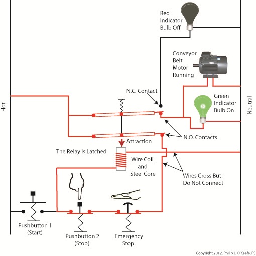
Figure 2
The circuit in Figure 2 represents what happens after Button 1 is depressed. That is, the electric relay has become latched and current flows between hot and neutral sides through one of the N.O. contacts along the path of the green indicator bulb, the motor overload relay heater, and the conveyor belt motor. The current also flows through the other N.O. contact, the Emergency Stop button, Button 2, the electric relay’s wire coil, and the motor overload relay bimetal contacts. The motor becomes overloaded, causing the overload relay heater to produce abnormally high heat. This heat is directed towards the bimetal contacts, also causing them to heat up.
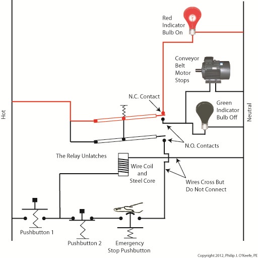
Figure 3
In Figure 3 the bimetal contacts have heated to the point that they have curled away from each other until they no longer touch. With the bimetal contacts open, electric current is unable to flow through to the electric relay’s wire coil. This in turn ends the magnetic attraction which formerly held the relay armatures against the N.O. contacts. The spring in the electric relay has pulled the armatures up, causing the N.O. contacts to open, simultaneously closing the N.C. contact. These actions have resulted in a loss of current to the green indicator bulb and electric motor. The red indicator bulb is now activated, and the conveyor motor is caused to automatically shut down to prevent damage and possible fire due to overheating. This means that even if the conveyor operator were to immediately press Button 1 in an attempt to restart the line, he would be prevented from doing so. Under these conditions the electric relay is prevented from latching, and the motor remains shut down because the bimetal contacts have been separated, preventing current from flowing through to the wire coil. The bimetal contacts will remain open until they once again cool to normal operating temperature. Once cooled, they will once again close, and the motor can be restarted. If the cause of the motor overload is not diagnosed and its ability to recur eliminated, the automatic shutdown process will repeat this cycle. Next time we’ll see how the overload relay is represented in a ladder diagram. We’ll also see how switches can be added to the circuit to allow maintenance staff to safely work. ____________________________________________
|


Industrial Control Basics – Thermal Expansion Effect on Overload Relays
Sunday, March 11th, 2012| Imagine driving on steel tires, not rubber. Don’t think it would work too well? On asphalt highways maybe not, but on the steel rails that steam locomotives travel upon, steel wheels work surprisingly well and it’s due in large part to the principles of thermal expansion and the different rates at which metal alloys expand and contract. Allow me to explain by analyzing how a locomotive“tire” is changed.
As you can imagine changing locomotive tires isn’t easy. Firstly, locomotive shop mechanics have to actually build a fire around the steel tire to heat it up. The intense heat causes its steel tire to thermally expand, meaning its steel molecules become energized by the heat and begin to vibrate. This causes the molecules to move away from each other, and this results in the tire actually growing slightly in size. This enlargement is just enough to enable mechanics to slip the tire back onto the locomotive’s wheel. Now in place, the tire is allowed to cool back down to ambient air temperatures. Cooling results in the tire’s steel molecules relaxing and moving closer to each other. The tire shrinks back to its original preheated size and tightly wraps itself around the wheel. Thermal expansion properties of metals comes into play in many other instances, including the workings of motor overload relays. Please refer to Figure 1.
Figure 1
Here overload relay components are shown in the foreground box. We see that the relay includes an electric heater and a set of two peculiar looking curved objects. These are bimetal switch contacts, so named because each is made of two, that’s the “bi” part, metal strips with different thermal properties. These strips are positioned back to back, then bonded together and curved into a shape resembling a question mark. Each of the two metals has different properties, namely, one expands at a faster rate and to a greater extent than the other when heated. This differing rate of expansion is indicative of the two metals’ diverse thermal properties. When the bimetal contact is exposed to heat, one metal strip wants to expand a lot, but it is bonded to the other metal strip which only wants to expand a little. The end result is that their point of contact distorts and changes shape. When allowed to cool back down, the metal strips contract and the contact point returns to its original shape. In our next blog we’ll see how the contact shape changes and why this shape change is important. In Figure 1 the motor is running normally and there is no overload situation. Under these conditions the motor draws electric current within the normal limits of its design. That current also flows through the heater in the overload relay causing it to generate heat, but in this situation the heat change is small enough that it doesn’t affect the bimetal switch contacts and cause them to change shape. The temperature at which the switch contacts will warp depends on the overall design of the overload relay as well as its application. Next time we’ll see what part a motor overload plays in conjunction with the overload relay’s heater and bimetal contacts. ____________________________________________
|

Industrial Control Basics – Motor Overload
Sunday, March 4th, 2012|
Last summer my wife and I did a lot of work in the garden. Many holes were dug, bags of garden soil lifted, and plants planted. It’s a new garden, and my wife has very big plans for it, so needless to say there was a lot of work to be done. On more than one occasion we would end the day moaning about our body aches and how we had overdone it. The next day we would hurt even worse, and we’d end up taking time off to recuperate. Pain is your body’s way of telling you that it needs attention, and you’d better listen to it or you may have an even heavier price to pay down the road. Electric motors can get overworked, just like our bodies. Motors are often placed into situations where they are expected to perform tasks beyond their capability. Sometimes this happens through poor planning, sometimes due to wishful thinking on the user’s part. Motors can sustain damage when stressed in this way, but they don’t have a pain system to tell them to stop. Instead, motors benefit by a specific type of electric relay known as an overload relay. But before we get into how an overload relay works, let’s get a better understanding of how overloads happen. Suppose we’re back in the telephone factory discussed in previous blogs, watching a conveyor belt move phones through the manufacturing process. An electric motor drives the conveyor belt by converting electrical energy into mechanical energy. Everything is moving along normally when all of a sudden a machine malfunctions. Telephones start piling up on a belt, and the pile up gets so bad the belt eventually gets jammed and its motor overloaded. If the electricity flow to the motor isn’t shut down promptly by means of a nearby emergency stop button or an astute operator sitting in central control, then an even bigger problem is in the making, that of a potential fire. When electricity is applied to motors they begin to operate, and their natural tendency is to want to keep operating. They do so by continuously drawing energy from the electric current being supplied to them. The greater the workload demand on the motor, the more current it requires to operate. When motors become overloaded as in the scenario presented above, they continue to draw energy unless forced to a stop. The result is an overabundance of current flowing through the motor and no outlet for its task of converting electrical energy into mechanical energy. And where is all that pent up energy to go? It becomes heat energy trapped inside the motor itself, and this heat can build up to the point where the motor becomes damaged or even bursts into flames. Next time we’ll look at how overload relays work to keep electric motors from overheating, just as our body’s pain sensors protect us from overdoing it.
____________________________________________
|


