Archive for September, 2017

What Came First? The Wheel or the Flywheel?

Monday, September 25th, 2017

   What came first?   The wheel or the flywheel?  Archeologists have been debating this question for decades.   One thing is certain, they both date back to prehistoric times.

What Came First? The Wheel or the Flywheel?

What Came First? The Wheel or the Flywheel?


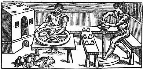
   One of the oldest flywheel discoveries was a potter’s wheel, used to make pottery.   It’s a turntable made of stone or heavy wood that’s connected to a massive wheel by a spinning shaft.   Once the potter got the flywheel spinning with his hand or foot, the wheel’s heavy weight kept it in virtual perpetual motion, allowing the potter to concentrate on forming the clay he shaped with his hands.

   A potter’s wheel, or any other flywheel for that matter, takes a lot of initial effort to put into motion.   In other words, the potter must put a lot of his own muscles’ mechanical energy into the flywheel to get it moving.   That’s because its sheer weight binds it to the Law of Inertia and makes it want to stay at rest.

   But once the flywheel is in motion, the potter’s mechanical energy input is transformed into kinetic energy, the energy of motion.   The kinetic energy the potter produces by his efforts results in surplus energy stored within the flywheel.   Hence, the flywheel serves as a kinetic energy storage device, similar to a battery which stores electrical energy.   As long as the flywheel remains in motion, this stored energy will be used to keep the turntable spinning, which results in no additional mechanical energy needing to be exerted by the potter while forming pots.

   The flywheel’s stored energy also makes it hard to stop once it’s in motion.   But eventually the frictional force between the potter’s hands and the clay he works drains off all stored kinetic energy.

   Since the Industrial Revolution flywheels have been used to store kinetic energy to satisfy energy demands and provide a continuous output of power, which increases mechanical efficiency.

   Next time we’ll begin our exploration into the science behind flywheels and see how they’re used in diverse engineering applications.


Copyright 2017 – Philip J. O’Keefe, PE

Engineering Expert Witness Blog

____________________________________


Optimizing Belt Width in a Pulley-Belt Assembly

Friday, September 15th, 2017

   It’s been awhile since we began our discussion of a pulley-belt assembly operating within a hydroponics plant, and we’ve solved for a lot variables and derived many equations along the way.   Today we’ll tackle the two remaining variables,  T1 , the belt’s tight side tension, and T2 , its loose side tension, and we’ll determine exactly what belt width will optimize power transmission within our system.

 Optimizing Belt Width in a Pulley-Belt Assembly

Optimizing Belt Width in a Pulley-Belt Assembly


   Last time we converted mechanical power, P, from horsepower into foot-pounds per second and the belt’s velocity, V, into feet per second in order to get things into terms we can work with.   We then inserted these values into the mechanical power formula to get,

2,200 foot pounds per second = (T1 – T2) × 3.93 feet/second               (1)

   This equation will allow us to solve for T1 and T2, and from there we’ll develop a value for the optimum belt width.

   Previously, we determined from the Euler-Eytelwein Formula that,

T1 = 2.38T2                                                                                     (2)

   Substituting equation (2) into equation (1), we get,

2,200 foot pounds per second = (2.38T2  – T2) × 3.93 feet/second      (3)

   Reducing this equation with algebra we arrive at,

T2 = 405.65 pounds                                                                         (4)

   We can now insert equation (4) into equation (2) and calculate T1,

T1 = 2.38 × 405.65 pounds                                                               (5)

T1 = 965.44 pounds                                                                         (6)


   T1 is maximum tension in the belt, specified by the manufacturer to be 300 pounds per inch of width, which makes the minimum width belt to be used to optimize power transmission within our  pulley-belt assembly,

w = T1 ÷ 300 pounds per inch                                                           (7)

w = 965.44 pounds ÷ 300 pounds per inch                                         (8)

w = 3.22 inches                                                                                (9)

   We can use a belt of minimum width of 3.22 inches to safely transmit 4 horsepower from the engine to the pump without incurring breakage and slippage along the belt, thereby optimizing power transmission within our assembly.   If we used a narrower belt, breaking and slippage would occur.   If we used a wider belt, an unnecessary expense would be incurred.

   Next time we’ll begin a discussion on flywheels as they apply to rotating machinery like gasoline and steam engines.


Copyright 2017 – Philip J. O’Keefe, PE

Engineering Expert Witness Blog

____________________________________


Unit Conversion, Horsepower to Foot-Pounds per Second

Monday, September 4th, 2017

   We’ve been working our way towards developing values for variables in our example pulley-belt assembly, and last time we calculated the velocity of the belt in that assembly to be 237.99 feet per minute.   But before we can go on to calculate the belt’s loose side tension, T2, and tight side tension, T1, we’ll need to discuss unit conversion, specifically how to convert horsepower into foot-pounds per second.

   Our working formula for this demonstration is the formula for mechanical power, P, previously introduced and shown again here,

P = (T1 – T2) × V                                                               (1)

   By engineering convention mechanical power is normally measured in units of foot-pounds per second.   But if you’ll recall from a past blog in which we determined the belt’s velocity, V, it was measured in units of feet per minute, not per second. 

   To further complicate things, the difference in belt tensions, T1 – T2, is stated in units of pounds, and combining these elements together results in P being expressed in foot-pounds per minute, not the required per second, because we are multiplying feet per minute by pounds.   That’s a whole lot of unit changing within a single equation, which makes for an awkward situation.

   To smooth things out we’ll have to do some converting of units.   We’ll start by dividing V by 60 seconds per minute so it can be expressed in units of feet per second,

V = 237.99 feet per minute ÷  60 seconds per minute          (2)

 V = 3.93 feet/second                                                        (3)

   The power in our belt was previously given as 4 horsepower, which must also undergo conversion and be put in terms of foot-pounds per second so it can be used in equation (1).

Unit Conversion, Horsepower into Foot-Pounds

Unit Conversion, Horsepower to Foot-Pounds per Second


   One horsepower is equal to 550 foot-pounds per second, which makes the amount of power, P, in our pulley-belt assembly equal to 2,200 foot-pounds per second.

   Units converted, we can now insert the values for V and P into equation (1) to arrive at,

2,200 foot pounds per second = (T1 – T2) × 3.93 feet/second           (4)

   Next time we’ll use this relationship to develop values for T1 and T2, the belt’s tight and loose side tensions.

Copyright 2017 – Philip J. O’Keefe, PE

Engineering Expert Witness Blog

____________________________________