Posts Tagged ‘horsepower’
Thursday, December 21st, 2017
|
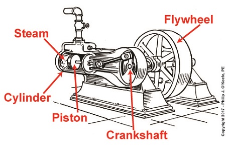
Last time we had a look inside a marvelous piece of engineering machinery known as a crankshaft. It plays a key role in converting the reciprocating linear motion of a steam driven engine into the rotary motion required to power externally mounted devices that are attached to it. Today we’ll finish up our blog series on flywheels when we see how using one in conjunction with a crankshaft facilitates a more even transmission of energy. Reciprocating engines maximize efficiency when they employ flywheels.
We learned that the energy in the steam supply decreases as the piston moves in its cylinder, which means a concurrent decrease in the engine’s horsepower and its ability to power machinery. Without an intervening action, the reciprocating steam engine would stall. Now, let’s see how adding a flywheel to the crankshaft can solve the problem.
Reciprocating Engines Maximize Efficiency When They Employ Flywheels
As we’ve learned before, a flywheel stores up kinetic energy while the engine powering it is performing at full horsepower, but if that power should drop off or cease to be produced, the flywheel gives up the kinetic energy stored inside it so as to keep externally mounted machinery operating until that stored energy is exhausted. This is all made possible because flywheels are designed to have moments of inertia sufficient to positively contribute to its storage of kinetic energy. This inertia is a numerical representation of the flywheel’s resistance to change in motion. Please review our past blog on the subject to refresh your memory.
The overall effect is that while the engine is operating, there’s an even flow of energy between the engine and flywheel and horsepower is supplied to keep machinery mounted to the crankshaft operating. Any diminishment in the power supplied will be compensated for by the flywheel’s stored kinetic energy.
Next time we’ll introduce a new topic, a phenomenon known as cavitation.
opyright 2017 – Philip J. O’Keefe, PE
Engineering Expert Witness Blog
____________________________________ |
Tags: crankshaft, efficiency, engineering, flywheel, horsepower, kinetic energy, moment of inertia, reciprocating steam engine
Posted in Engineering and Science, Expert Witness, Forensic Engineering, Innovation and Intellectual Property, Personal Injury, Product Liability | Comments Off on Reciprocating Engines Maximize Efficiency When They Employ Flywheels
Friday, November 24th, 2017
|
Last time we discussed how torque is created as a flywheel spins. This torque is a factor of the flywheel’s moment of inertia, which is dependent on how far the masses of the flywheel’s parts are located from its center of rotation. Today we’ll present a formula to compute how much horsepower is required to accelerate a flywheel. And here it is,

Horsepower Required to Accelerate a Flywheel
where, T is the torque created on the flywheel’s shaft in units of inch-pounds. The term n is the flywheel shaft’s speed of rotation in revolutions per minute, RPM. Horsepower, HP, is engineering shorthand for a unit of power equal to 6600 inch-pounds per second, and the number 63,025 is a constant needed to convert torque, T, and the spinning shaft’s rotations per minute, RPM, into horsepower units.
Torque is present whether the flywheel’s spin accelerates or decelerates. During acceleration torque is created, which contributes to the production of kinetic energy that’s stored inside the flywheel. When a flywheel’s spin decelerates, its mass experiences the effects of negative acceleration, and stored kinetic energy is released.
As we learned awhile back, horsepower is a function of torque in any moving machinery, including engines and flywheels. An engine must produce horsepower to accelerate a flywheel connected to its shaft. By the same token, when the engine’s horsepower output diminishes or stops, the flywheel begins to decelerate. This deceleration causes kinetic energy stored within the flywheel to be released, providing horsepower necessary to keep the engine and flywheel spinning. That is, until the power output of the engine returns or the stored kinetic energy of the flywheel is ultimately exhausted.
We’ll see how that works next time when we take a look inside a reciprocating engine.
opyright 2017 – Philip J. O’Keefe, PE
Engineering Expert Witness Blog
____________________________________ |
Tags: acceleration, deceleration, engine, engineering, flywheel, horsepower, kinetic energy, mass, moment of inertia, torque
Posted in Engineering and Science, Expert Witness, Forensic Engineering, Innovation and Intellectual Property, Personal Injury, Product Liability | Comments Off on Horsepower Required to Accelerate a Flywheel
Monday, September 4th, 2017
|
We’ve been working our way towards developing values for variables in our example pulley-belt assembly, and last time we calculated the velocity of the belt in that assembly to be 237.99 feet per minute. But before we can go on to calculate the belt’s loose side tension, T2, and tight side tension, T1, we’ll need to discuss unit conversion, specifically how to convert horsepower into foot-pounds per second.
Our working formula for this demonstration is the formula for mechanical power, P, previously introduced and shown again here,
P = (T1 – T2) × V (1)
By engineering convention mechanical power is normally measured in units of foot-pounds per second. But if you’ll recall from a past blog in which we determined the belt’s velocity, V, it was measured in units of feet per minute, not per second.
To further complicate things, the difference in belt tensions, T1 – T2, is stated in units of pounds, and combining these elements together results in P being expressed in foot-pounds per minute, not the required per second, because we are multiplying feet per minute by pounds. That’s a whole lot of unit changing within a single equation, which makes for an awkward situation.
To smooth things out we’ll have to do some converting of units. We’ll start by dividing V by 60 seconds per minute so it can be expressed in units of feet per second,
V = 237.99 feet per minute ÷ 60 seconds per minute (2)
V = 3.93 feet/second (3)
The power in our belt was previously given as 4 horsepower, which must also undergo conversion and be put in terms of foot-pounds per second so it can be used in equation (1).

Unit Conversion, Horsepower to Foot-Pounds per Second
One horsepower is equal to 550 foot-pounds per second, which makes the amount of power, P, in our pulley-belt assembly equal to 2,200 foot-pounds per second.
Units converted, we can now insert the values for V and P into equation (1) to arrive at,
2,200 foot pounds per second = (T1 – T2) × 3.93 feet/second (4)
Next time we’ll use this relationship to develop values for T1 and T2, the belt’s tight and loose side tensions.
Copyright 2017 – Philip J. O’Keefe, PE
Engineering Expert Witness Blog
____________________________________ |
Tags: belt, belt and pulley assembly, belt velocity, engineering, foot pounds per second, horsepower, loose side tension, mechanical power, pulley, tight side tension, unit conversions, units
Posted in Engineering and Science, Expert Witness, Forensic Engineering, Innovation and Intellectual Property, Personal Injury, Product Liability | Comments Off on Unit Conversion, Horsepower to Foot-Pounds per Second
Friday, June 23rd, 2017
|
Belts are important. They make fashion statements, hold things up, keep things together. Today we’re introducing a scenario in which the Euler-Eytelwein Formula will be used to, among other things, determine the ideal width of a belt to be used in a mechanical power transmission system consisting of two pulleys inside a hydroponics plant. The ideal width belt would serve to maximize friction between the belt and pulleys, thus controlling slippage and maximizing belt strength to prevent belt breakage.
An engineer is tasked with designing an irrigation system for a hydroponics plant. Pulley 1 is connected to the shaft of a water pump, while Pulley 2 is connected to the shaft of a small gasoline engine.
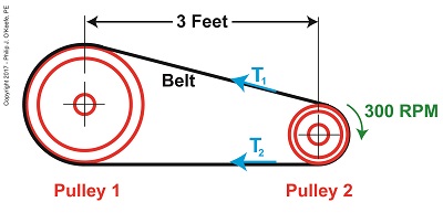
What Belt Width does a Hydroponics Plant Need?
Mechanical power is transmitted by the belt from the engine to the pump at a constant rate of 4 horsepower. The belt material is leather, and the two pulleys are made of cast iron. The coefficient of friction, μ, between these two materials is 0.3, according to Marks Standard Handbook for Mechanical Engineers. The belt manufacturer specifies a safe working tension of 300 pounds force per inch width of the belt. This is the maximum tension the belt can safely withstand before breaking.
We’ll use this information to solve for the ideal belt width to be used in our hydroponics application. But first we’re going to have to re-visit the two T’s of the Euler-Eytelwein Formula. We’ll do that next time.
Copyright 2017 – Philip J. O’Keefe, PE
Engineering Expert Witness Blog
____________________________________ |
Tags: belt, belt breakage, coefficient of friction, engine, engineer, horsepower, leather belt, mechanical power transmission, pulley, pump
Posted in Engineering and Science, Expert Witness, Forensic Engineering, Innovation and Intellectual Property, Personal Injury, Product Liability | Comments Off on What Belt Width does a Hydroponics Plant Need?
Friday, August 15th, 2014
|
Hold onto your hats, we’re going to deal with a lot of equations today!
Last time we used flashbacks to previous blogs in this series to revisit key equations in our ongoing discussion of gear trains and torque. We also introduced The Law of Conservation of Energy in conjunction with five equations that together demonstrate how when increasing torque by use of a simple gear train, we do so at the cost of speed.
Those five equations are:
| R = NDriven ÷ NDriving = nDriving ÷ nDriven |
(1) |
|
|
| TDriving ÷ TDriven = DDriving ÷ DDriven |
(2) |
|
|
| TDriving = [HPDriving ÷ nDriving] × 63,025 |
(3) |
|
|
| TDriven = [HPDriven ÷ nDriven] × 63,025 |
(4) |
|
|
| HPDriving = HPDriven |
(5) |
where, R is the gear ratio, N the number of gear teeth, n the gear’s rotational speed, T the torque, D the gear pitch radius, and HP is the horsepower transmitted by the gears.

As we work the equations, keep in mind that our ultimate objective is to find a way to link together (1) and (2), the equations dealing with gear torque and speed. Once we accomplish this we’ll see how increased torque is obtained at the cost of speed. But because there are no common terms between equations (1) and (2), our first step is to develop one.
Developing a link between equations (1) and (2) is a process that begins with combining equations (2), (3), and (4).
| TDriving ÷ TDriven = DDriving ÷ DDriven |
(2) |
|
|
| TDriving = [HPDriving ÷ nDriving] × 63,025 |
(3) |
|
|
| TDriven = [HPDriven ÷ nDriven] × 63,025 |
(4) |
The common terms in these three equations are TDriving and TDriven, so we’ll manipulate things in order to group them together. We’ll substitute equation (3) for the TDriving term in equation (2), and substitute equation (4) for the TDriven term in equation (2). We are now able to link all three equations to get:
{[HPDriving ÷ nDriving] × 63,025} ÷ {[HPDriven ÷ nDriven] × 63,025}
= DDriving ÷ DDriven (6)
Now let’s go a step further to simplify equation (6). From equation (5) we know that the driving and driven gear horsepowers are equal. So, in equation (6), the HPDriving and HPDriven cancel out, along with the two 63,025 terms, allowing us to arrive at equation (7):
{[HPDriving ÷ nDriving] × 63,025} ÷ {[HPDriven ÷ nDriven] × 63,025}
= DDriving ÷ DDriven
| nDriven ÷ nDriving = DDriving ÷ DDriven |
(7) |
Next week we’ll use equation (7) to link together R, N, n, of equation (1) with D and T of equation (2) and in so doing disclose mathematically the tradeoff between torque and speed, then apply our findings to an example.
_______________________________________
|
Tags: driven gear, driving gear, electric motor, engineering blog, engineering expert witness, forensic engineer, gear equations, gear expert, gear formula, gear ratio, gear speed, gear train, gears, horsepower, law of conservation of energy, mechanical engineer expert witness, number of teeth, pitch diameter, torque
Posted in Engineering and Science, Expert Witness, Forensic Engineering, Innovation and Intellectual Property, Personal Injury, Product Liability | Comments Off on Determining the Gear Train Tradeoff of Torque vs. Speed, Part One
Tuesday, August 5th, 2014
|
We’ve learned several methods to increase the torque of an electric motor through our series of articles on gear trains. One way is to attach a gear train to the motor’s shaft, a relatively simple thing to do. Today we’ll begin our exploration into how this method involves a tradeoff. It comes at the cost of speed.
We’ll begin our examination of the tradeoff at play by linking together key elements learned through past blogs on the subject of gear trains. We’ll revisit those lessons through flashbacks.

The first flashback we’ll make is to a blog entitled, Gear Ratio Formulas. There we learned that within a simple gear train consisting of two gears, the type most commonly employed to manipulate a motor’s torque, the ratio between the two gears, R, is relative to the ratio of their gear teeth, N. N is determined by the number of teeth each gear has in combination with the speeds, n, that each gear is going:
R = NDriven ÷ NDriving = nDriving ÷ nDriven (1)
The second flashback we’ll make is to a blog entitled, The Methodology Behind Gear Train Torque Conversions, in which we learned that the ratio of the torque, T, that exists between the gears is relative to the ratio of their respective pitch diameters, D:
TDriving ÷ TDriven = DDriving ÷ DDriven (2)
The tradeoff we’ve been alluding to comes in when gear speed, nDriven, represented in equation (1), is decreased, which results in an increase to TDriven in equation (2). But in order to see this we’ve got to somehow link the two equations together. In their present form there’s no common link between them. Or is there?
There actually is an indirect link between the two equations, which comes by way of the torque equation presented in another past blog. The third flashback we’ll make is to the blog discussing that subject, which is entitled, The Relationship Between Torque and Horsepower. Using facts presented in that blog, the torque equations for our two gears become:
TDriving = [HPDriving ÷ nDriving] × 63,025 (3)
TDriven = [HPDriven ÷ nDriven] × 63,025 (4)
Where’s the link between equations (1) and (2)? To answer that question we must reference a physics law known as The Law of Conservation of Energy . It states that the energy flowing from one gear to another within a gear train remains constant. Energy equates to horsepower, HP, in equations (3) and (4). So if the horsepower flowing through the gears is equal, our working equation becomes:
HPDriving = HPDriven (5)
Next time we’ll see how equation (5) is key to linking together equations (1) and (2) by way of equations (3) and (4). In so doing we’ll disclose the tradeoff to using gear trains.
_______________________________________
|
Tags: conservation of energy, driven gear, driving gear, engineering expert witness, forensic engineer, gear expert witness, gear pitch diameter, gear speed, gear teeth, gear train, gears, horsepower, horsepower equation, licensed professional engineer, mechanical engineering expert witness, motor shaft, physics, torque, torque conversion, torque equation
Posted in Engineering and Science, Expert Witness, Forensic Engineering, Innovation and Intellectual Property, Product Liability | Comments Off on The Gear Train Tradeoff
Monday, July 28th, 2014
|
Last time we learned that we can get more torque out of a motor by using one of two methods. In the first method we attach a gear train to the motor, then try different gear sizes until we arrive at the desired torque for the application. In the second method we eliminate the gear train altogether and simply use a higher horsepower motor to give us the torque we need.
Today we’ll explore the second method. We’ll use the equation presented in our last blog to determine torque, T, relative to a motor’s horsepower, HP, when the motor operates at a speed, n:
T = [HP ÷ n] × 63,025
In earlier blogs in this series we employed a gear train attached to an electric motor to power a lathe. It provided an insufficient 200 inch pounds of torque when 275 is required. Let’s use the equation and a little algebra to see how much horsepower this motor develops if it turns at a speed of 1750 RPM, a common speed for alternating current (AC) motors:
200 inch pounds = [HP ÷ 1750 RPM] × 63,025
200 = HP × 36.01
HP = 200 ÷ 36.01 = 5.55 horsepower
For the purpose of our example today, let’s say we’ve nonsensically decided not to use a gear train, leaving us with no choice but to replace the underpowered motor with a more powerful one. So let’s see what size motor we’ll need to provide us with the required horsepower of 275 inch pounds.

Using the torque equation and plugging in numbers already provided our equation becomes:
275 inch pounds = [HP ÷1750 RPM] × 63,025
275 = HP × 36.01
HP = 275 ÷ 36.01 = 7.64 horsepower
This tells us that we need to replace the 5.55 horsepower motor with a 7.65 horsepower motor.
As you might have guessed, the higher the motor’s horsepower, the larger that motor’s size and weight — if you’re not using a gear train, that is. Bigger, bulkier motors cost more to purchase and operate and also take up more space, which often makes them impractical to use.
All this translates to the reality that sometimes it just makes more sense to use a gear train to provide more torque. It’s a lot easier and cheaper to attach a gear train to a motor and manipulate its gear sizes to arrive at desired torque than it is to buy a bigger motor.
You may have deduced by now that it’s relatively easy to get more torque. Almost too easy. Next time we’ll see how increased torque comes at another type of cost, the cost of speed.
_______________________________________
|
Tags: electric motor, engineering expert witness, forensic engineer, gear sizes, gear train, horsepower, mechanical engineer, motor, motor speed, torque, torque equation
Posted in Engineering and Science, Expert Witness, Forensic Engineering, Innovation and Intellectual Property, Personal Injury, Product Liability | Comments Off on Equations Used to Manipulate Torque Relative to Horsepower
Tuesday, July 15th, 2014
| We’ve been discussing gear trains for some time now, and last time we posed the question: Why even bother using a gear train and performing complex computations to arrive at a desired torque for an application? Why not just use a bigger motor to start with? Today we’ll see why.
First, we must acknowledge that sometimes higher torque is achieved by simply using a more powerful motor. But sometimes this isn’t possible or practical.
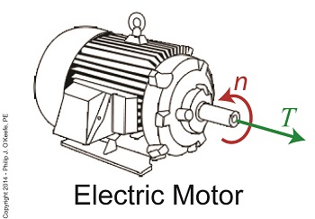
To begin our discussion, we must first understand how torque is related to motor power, the amount of mechanical work a motor can perform. Torque is in fact a function of how much mechanical power a motor produces. In the United States motor power is typically measured in units of horsepower.
The following equation illustrates the relationship between torque, horsepower, and motor speed:
T = [HP ÷ n] × 63,025
where T is the motor shaft’s torque in units of inch-pounds, HP is the motor’s horsepower, and n is the speed of the motor shaft in revolutions per minute (RPM). The number 63,025 in the equation is a constant used to convert the units of horsepower and RPM into units of torque (inch pounds). This equation applies to all sources of mechanical power. Its versatility enables design engineers to easily determine if a mechanical power source can deliver the torque required to drive a particular piece of machinery.
The torque equation above tells us that in order to get a higher torque T for a given speed n, you’ll have to get a motor with a higher HP. Put another way, if your speed remains constant and you use a motor with higher horsepower, you’ll get more torque for your application simply by increasing the horsepower.
Next time we’ll plug numbers into our equation and see how it all works.
_______________________________________
|
Tags: electric motor, engineering expert witness, forensic engineer, gear train, horsepower, machinery, mechanical power, motor shaft, motor shaft torque, motor speed, torque
Posted in Engineering and Science, Expert Witness, Forensic Engineering, Innovation and Intellectual Property, Personal Injury, Product Liability, Professional Malpractice | Comments Off on The Relationship Between Torque and Horsepower
Sunday, June 22nd, 2014
|
Last time we learned that gear trains are torque converters, and we developed a torque ratio equation which mathematically ties the two gears in a gear train together. That equation is:
T1 ÷ T2 = D1 ÷ D2
Engineers typically use this equation knowing only the value for T2, the torque required to properly drive a piece of machinery. That knowledge is acquired through trial testing during the developmental phase of manufacturing.
Once T2 is known, a stock motor is selected from a catalog with a torque value T1 which closely approximates that of the required torque, T2. Then calculations are performed and lab tests are run to determine the driving and driven gear sizes, D1 and D2 which will enable the gear train to convert T1 into the required value of T2. This series of operations are often a time consuming and complex process.
To simplify things for the purpose of our example, we’ll say we’ve been provided with all values required for our equation, except one, the value of T2. In other words, we’ll be doing things in a somewhat reverse order, because our objective is simply to see how a gear train converts a known torque T1 into a higher torque T2.

We’ll begin by considering the gear train illustration above. For our purposes it’s situated between an electric motor and the lathe it’s powering. The motor exerts a torque of 200 inch pounds upon the driving gear shaft of the lathe, a torque value that’s typical for a mid sized motor of about 5 horsepower. As-is, this motor is unable to properly drive the lathe, which is being used to cut steel bars. We know this because lab testing has shown that the lathe requires at least 275 inch pounds of torque in order to operate properly.
Will the gears on our gear train be able to provide the required torque? We’ll find out next time when we insert values into our equation and run calculations.
_______________________________________
|
Tags: calculations, driven gear, driving gear, driving gear shaft, electric motor, engine lathe, engineering, engineering expert witness, forensic engineer, gear expert, gear train, gears, horsepower, lab testing, lathe, machinery expert, motor torque, shaft, torque, torque calculations, torque converter
Posted in Engineering and Science, Expert Witness, Forensic Engineering, Innovation and Intellectual Property, Personal Injury, Product Liability | Comments Off on The Methodology Behind Gear Train Torque Conversions
Wednesday, December 4th, 2013
|
Last time we ran our basic power plant steam turbine without a condenser. In that configuration the steam from the turbine exhaust was simply discharged to the surrounding atmosphere. Today we’ll connect it to a condenser to see how it improves the turbine’s efficiency.

As discussed in a previous blog, enthalpy h1 is solely dependent on the pressure and temperature at the turbine inlet. For purposes of today’s discussion, turbine inlet steam pressure and temperature will remain as last time, with values of 2,000 lbs PSI and 1000°F respectively, and calculations today will be based upon those values. So to review, the inlet enthalpy h1 is,
h1 = 1474 BTU/lb
If the condenser vacuum exists at a pressure of 0.6 PSI, a realistic value for a power plant condenser, then referring to the steam tables in the Van Wylen and Sonntag thermodynamics book, we find that the enthalpy h2 will be,
h2 = 847 BTU/lb
and the amount of useful work that the turbine can perform with the condenser in place would therefore be,
W = h1 – h2 = 1474 BTU/lb – 847 BTU/lb = 627 BTU/lb
So essentially with the condenser present, the work of the turbine is increased by 168 BTU/lb (627 BTU/lb – 459 BTU/lb). To put this increase into terms we can relate to, consider this. Suppose there’s one million pounds of steam flowing through the turbine each hour. Knowing this, the turbine power increase, P, is calculated to be,
P = (168 BTU/lb) ´ (1,000,000 lb/hr) = 168,000,000 BTU/hr
Now according to Marks’ Standard Handbook for Mechanical Engineers, a popular general reference book in mechanical engineering circles, one BTU per hour is equivalent to 0.000393 horsepower, or HP. So converting turbine power, P, to horsepower, HP, we get,
P = (168,000,000 BTU/hr) ´ (0.000393 HP/BTU/hr) = 66,025 HP
A typical automobile has a 120 HP engine, so this equation tells us that the turbine horsepower output was increased a great deal simply by adding a condenser to the turbine exhaust. In fact, it was increased to the tune of the power behind approximately 550 cars!
What all this means is that the stronger the vacuum within the condenser, the greater the difference between h1 and h2 will be. This results in increased turbine efficiency and work output, as evidenced by the greater numeric value for W. Put another way, the turbine’s increased efficiency is a direct result of the condenser’s vacuum forming action and its recapturing of the steam that would otherwise escape from the turbine’s exhaust into the atmosphere.
This wraps up our series on the power plant water-to-steam cycle. Next time we’ll use the power of 3D animation to turn a static 2D image of a centrifugal clutch into a moving portrayal to see how it works.
________________________________________
|
Tags: automobile engine, BTU, BTU/lb, coal power plant, energy, engineering expert witness, enthalpy, forensic engineer, horsepower, mechanical engineer, power, power engineer, power industry expert, power plant efficiency, power plant expert, power plant training instructor, power plant training seminars, steam pressure, steam turbine, steam turbine expert witness, steam water cycle, thermodynamics, vacuum, work
Posted in Engineering and Science, Expert Witness, Forensic Engineering, Innovation and Intellectual Property, Personal Injury, power plant training, Product Liability, Professional Malpractice | Comments Off on How Condensers Increase Efficiency Inside Power Plants


