Posts Tagged ‘vacuum’
Thursday, February 8th, 2018
|
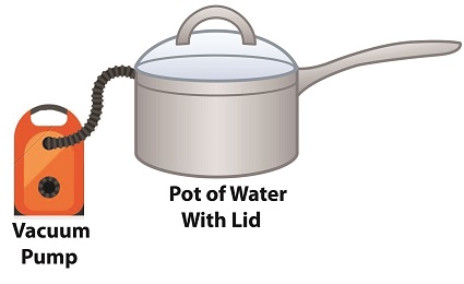
Last time we performed an engineering experiment that demonstrated how we can lower the boiling point of water inside a lidded pot without applying heat if we use a vacuum pump to lower the pot’s internal pressure. We discovered that when pressure was lowered to 0.25 pounds per square inch (PSI), the water inside the pot turned to steam at a mere 59ºF, which initiated the cavitation process. Today we’ll see how centrifugal pumps can also create vacuums to initiate cavitation.
Centrifugal Pumps Can Create Vacuums
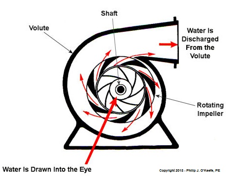
As we learned in a past blog, centrifugal pumps contain rotating impellers within a housing called a volute. This housing has an inlet, known as an eye, where water flows into the pump from a pipe, and an outlet, known as a discharge, where water flows out of the pump. The centrifugal pump creates a vacuum by mimicking the action of sucking soda through a straw. The spinning impeller draws water into the housing by creating low pressure at the inlet, and if the pressure gets low enough, we’ll recreate what happened in our vacuum pump and pot experiment. Water will boil at temps far lower than normal boiling point of 212 ºF. Just as in our experiment, if pressure is lowered to 0.23 PSI, water present at the pump inlet will boil at 59ºF, causing thousands of tiny steam bubbles to form and the pump to cavitate.
They’re just tiny bubbles, so what harm can they do? We’ll find out next time.
opyright 2018 – Philip J. O’Keefe, PE
Engineering Expert Witness Blog
____________________________________ |
Tags: boiling water, cavitation, centrifugal pump, engineering, low pressure, pump, vacuum
Posted in Engineering and Science, Expert Witness, Forensic Engineering, Innovation and Intellectual Property, power plant training, Product Liability | Comments Off on Centrifugal Pumps Can Create Vacuums
Sunday, January 28th, 2018
|
Last time we learned how the thermodynamic properties of water contribute to the phenomenon of cavitation, and how liquids exist in three states, solid, liquid, or vapor, depending on temperature and surrounding air pressure. Our example of an open pot of water being heated on a stove demonstrated that once water temperature rose above 212ºF, it changed to steam, which initiated the cavitation process. Today we’ll see how decreasing pressure contributes to cavitation.
How Decreasing Pressure Contributes to Cavitation
Cavitation can occur without a heat source. In our pot example, we can start the cavitation process by simply decreasing the pressure of the air resting on top of the water, thereby also decreasing the water’s pressure.
Normally atmospheric pressure on Earth exists at around 15 pounds per square inch (PSI). But if we introduce a vacuum pump to an enclosed space, we can create an internal pressure which is lower than the surrounding atmospheric pressure outside the pot. In other words, we create a vacuum. A vacuum is any air pressure lower than atmospheric pressure. This vacuum environment produces an entirely new set of circumstances under which cavitation can occur. In fact, creating a vacuum makes it possible to boil water without using any heat!
As we learned in a past blog on the different forms of heat energy, the boiling point of water varies depending on the location of the stovetop, whether it’s in a place of low altitude, like New Orleans, or higher altitude, like Denver. But if we apply a tight lid to the pot and isolate its internal atmosphere from surrounding atmospheric pressure, you create a closed environment. This allows us to manipulate the pot’s internal pressure. When we attach a vacuum pump to remove air, we reduce the air pressure bearing down on the water inside. With much of the air removed, pressure inside the pot drops below normal atmospheric pressure existing outside the pot, and we discover that at 0.25 PSI water turns to steam at a mere 59ºF and cavitation can begin. That’s right, you can boil water without using heat.
Next time we’ll apply our knowledge of water pressure and temperature to an industrial setting and see how cavitation occurs inside pumps.
opyright 2018 – Philip J. O’Keefe, PE
Engineering Expert Witness Blog
____________________________________ |
Tags: atmospheric pressure, cavitation, temperature, thermodynamics, vacuum
Posted in Engineering and Science, Expert Witness, Forensic Engineering, Innovation and Intellectual Property, Personal Injury, power plant training, Product Liability | Comments Off on How Decreasing Pressure Contributes to Cavitation
Wednesday, December 4th, 2013
|
Last time we ran our basic power plant steam turbine without a condenser. In that configuration the steam from the turbine exhaust was simply discharged to the surrounding atmosphere. Today we’ll connect it to a condenser to see how it improves the turbine’s efficiency.

As discussed in a previous blog, enthalpy h1 is solely dependent on the pressure and temperature at the turbine inlet. For purposes of today’s discussion, turbine inlet steam pressure and temperature will remain as last time, with values of 2,000 lbs PSI and 1000°F respectively, and calculations today will be based upon those values. So to review, the inlet enthalpy h1 is,
h1 = 1474 BTU/lb
If the condenser vacuum exists at a pressure of 0.6 PSI, a realistic value for a power plant condenser, then referring to the steam tables in the Van Wylen and Sonntag thermodynamics book, we find that the enthalpy h2 will be,
h2 = 847 BTU/lb
and the amount of useful work that the turbine can perform with the condenser in place would therefore be,
W = h1 – h2 = 1474 BTU/lb – 847 BTU/lb = 627 BTU/lb
So essentially with the condenser present, the work of the turbine is increased by 168 BTU/lb (627 BTU/lb – 459 BTU/lb). To put this increase into terms we can relate to, consider this. Suppose there’s one million pounds of steam flowing through the turbine each hour. Knowing this, the turbine power increase, P, is calculated to be,
P = (168 BTU/lb) ´ (1,000,000 lb/hr) = 168,000,000 BTU/hr
Now according to Marks’ Standard Handbook for Mechanical Engineers, a popular general reference book in mechanical engineering circles, one BTU per hour is equivalent to 0.000393 horsepower, or HP. So converting turbine power, P, to horsepower, HP, we get,
P = (168,000,000 BTU/hr) ´ (0.000393 HP/BTU/hr) = 66,025 HP
A typical automobile has a 120 HP engine, so this equation tells us that the turbine horsepower output was increased a great deal simply by adding a condenser to the turbine exhaust. In fact, it was increased to the tune of the power behind approximately 550 cars!
What all this means is that the stronger the vacuum within the condenser, the greater the difference between h1 and h2 will be. This results in increased turbine efficiency and work output, as evidenced by the greater numeric value for W. Put another way, the turbine’s increased efficiency is a direct result of the condenser’s vacuum forming action and its recapturing of the steam that would otherwise escape from the turbine’s exhaust into the atmosphere.
This wraps up our series on the power plant water-to-steam cycle. Next time we’ll use the power of 3D animation to turn a static 2D image of a centrifugal clutch into a moving portrayal to see how it works.
________________________________________
|
Tags: automobile engine, BTU, BTU/lb, coal power plant, energy, engineering expert witness, enthalpy, forensic engineer, horsepower, mechanical engineer, power, power engineer, power industry expert, power plant efficiency, power plant expert, power plant training instructor, power plant training seminars, steam pressure, steam turbine, steam turbine expert witness, steam water cycle, thermodynamics, vacuum, work
Posted in Engineering and Science, Expert Witness, Forensic Engineering, Innovation and Intellectual Property, Personal Injury, power plant training, Product Liability, Professional Malpractice | Comments Off on How Condensers Increase Efficiency Inside Power Plants
Tuesday, November 26th, 2013
|
Last time we learned that the amount of useful work, W, that a steam turbine performs is calculated by taking the difference between the enthalpy of the steam entering and then leaving the turbine. And in an earlier blog we learned that a vacuum is created in the condenser when condensate is formed. This vacuum acts to lower the pressure of turbine exhaust, and in so doing also lowers the enthalpy of the exhaust steam. Putting these facts together we are able to generate data which demonstrates how the condenser increases the amount of work produced by the turbine.
To better gauge the effects of a condenser, let’s look at the differences between its being present and not present. Let’s first take a look at how much work is produced by a steam turbine without a condenser.

The steam entering the turbine inlet has a pressure of 2000 pounds per square inch (PSI) and a temperature of 1000°F. Knowing these turbine inlet conditions, we can go to the steam tables in any thermodynamics book to find the enthalpy, h1. Titles such as Fundamentals of Classical Thermodynamics by Gordon J. Van Wylen and Richard E. Sonntag list enthalpy values over a wide range of temperatures and pressures. For our example this volume tells us that,
h1 = 1474 BTU/lb
where BTU stands for British Thermal Units, a unit of measurement used to quantify the energy contained within steam or water, in our case the water to steam cycle inside a power plant. Technically speaking, a BTU is the amount of heat energy required to raise the temperature of one pound of water by one degree Fahrenheit. The term lb should be a familiar one, it’s the standard abbreviation used for pound, so enthalpy is the measurement of the amount of energy per pound of steam flowing through, in this case, the turbine.
Since there is no condenser attached to the steam turbine’s exhaust in our illustration, the turbine discharges its spent steam into the surrounding atmosphere. The atmosphere in our scenario exists at 14.7 PSI because our power plant happens to be at sea level. Knowing these facts, the steam tables inform us that the value of the exhausted steam’s enthalpy, h2, is:
h2 = 1015 BTU/lb
Combining the two equations we are able to calculate the useful work the turbine is able to perform as:
W = h1 – h2 = 1474 BTU/lb – 1015 BTU/lb = 459 BTU/lb
This equation tells us that for every pound of steam flowing through it, the turbine converts 459 BTUs of the steam’s heat energy into mechanical energy to run the electrical generator.
Next week we’ll connect a condenser to the steam turbine to see how its efficiency can be improved.
________________________________________
|
Tags: British Thermal Unit, BTU, coal power plant expert, condensate, condenser, engineering expert witness, enthalpy, power engineer, power plant training seminar, pressure, steam, steam power plant, steam tables, steam turbine, steam turbine engineering expert witness, thermodynamics, turbine exhaust steam, vacuum, water, work
Posted in Engineering and Science, Expert Witness, Forensic Engineering, Innovation and Intellectual Property, Personal Injury, power plant training, Product Liability | Comments Off on Enthalpy Values in the Absence of a Condenser
Monday, November 18th, 2013
|
Last time we learned how enthalpy is used to measure heat energy contained in the steam inside a power plant. The higher the steam pressure, the higher the enthalpy, and vice versa, and we touched upon the concept of work, or the potential for a useful outcome of a process. Today we’ll see how to get the maximum work out of a steam turbine by attaching a condenser at the point of its exhaust and making the most of the vacuum that exists within its condenser.
Let’s revisit the equation introduced last time, which allows us to determine the amount of useful work output:
W = h1 – h2
Applied to a power plant’s water-to-steam cycle, enthalpy h1 is solely dependent on the pressure and temperature of steam entering the turbine from the boiler and superheater, as contained within the purple dashed line in the diagram below.

As for enthalpy h2, it’s solely dependent on the pressure and temperature of steam within the condenser portion of the water-to-steam cycle, as shown by the blue dashed circle of the diagram.
Next week we’ll see how the condenser, and more specifically the vacuum inside of it, sets the platform for increased energy production, a/k/a work.
________________________________________
|
Tags: boiler, coal power plant expert witness, condensate, condenser, electric generator, electric utility power plant expert, energy, engineering expert witness, enthalpy, forensic engineering, power engineering expert witness, power plant equipment, power plant training, steam pressure, steam temperature, steam turbine, superheater, turbine exhaust, turbine generator, vacuum, water-to-steam cycle, work
Posted in Engineering and Science, Expert Witness, Forensic Engineering, Innovation and Intellectual Property, Personal Injury, power plant training, Product Liability | Comments Off on Enthalpy and the Potential for More Work
Thursday, November 14th, 2013
|
Last time we learned how the formation of condensate within a power plant’s turbine results in a vacuum being created. This vacuum plays a key role in increasing steam turbine efficiency because it affects a property known as enthalpy, a term used to denote total heat energy contained within a substance. For the purposes of our discussion, that would be the heat energy contained within steam which flows through the turbine in a power plant.
The term enthalpy was first introduced by scientists within the context of the science of thermodynamics sometime in the early 20th Century. As discussed in a previous blog article, thermodynamics is the science that deals with heat and work present within processes. Enthalpy is a key factor in thermodynamics, and is commonly represented in engineering calculations by the letter h and denoted as,
h = u + Pv
where u is the internal energy of a substance, let’s say steam; P is the pressure acting upon a specific volume, v, of the steam; and P and v are multiplied together. Pressure is force per unit area and is measured in psi, pounds per square inch. For the purposes of our discussion, it’s the amount of pressure that steam places on pipes containing it.
Looking at the equation above, simple math tells us that if we increase the pressure, P, the result will be an increase in enthalpy h. If we decrease P, the result will be a decrease in h. Now, let’s see why this property is important with regard to the operation of a steam turbine.
When it comes to steam turbines, thermodynamics tells us that the amount of work they perform is proportional to the difference between the enthalpy of the steam entering the turbine and the enthalpy of the steam at the turbine’s exhaust. What is meant by work is the act of driving the electrical generator, which in turn provides electric power. In other words, the work leads to a useful outcome. This relationship is represented by the following equation,
W = h1 – h2
In terms of the illustration below, W stands for work, or potential for useful outcome of the turbine/generator process in the form of electricity, h1 is the enthalpy of the steam entering the inlet of the turbine from the superheater, and h2 is the enthalpy of the steam leaving at the turbine exhaust.

We’ll discuss the importance of enthalpy in more detail next week, when we’ll apply the concept to the work output of a steam turbine.
________________________________________
|
Tags: boiler, coal power plant, condensate, condenser, electrical generator, engineering expert witness, enthalpy difference, forensic engineer, heat energy, internal energy of steam, pipes, power plant design, power plant engineering expert, power plant operation, power plant training, pressure, specific volume of steam, steam pressure, steam turbine, steam turbine work, steam water cycle, superheater, thermodynamics, useful work, vacuum
Posted in Engineering and Science, Expert Witness, Forensic Engineering, Innovation and Intellectual Property, Personal Injury, power plant training, Product Liability | Comments Off on Enthalpy and Steam Turbines
Tuesday, November 5th, 2013
|
Last time we discussed the key functions of the make-up valve in the power plant water-to-steam cycle. Today we’re going to talk about a vacuum. No, not the kind you use around the house, the kind that’s created by the condenser inside a power plant.
As discussed previously, the condenser is a piece of equipment that turns turbine exhaust steam back into water. The water that’s formed during this process is known as condensate, and its density is higher than that of the steam it shares space with inside the condenser. That difference in density is what creates the vacuum inside the condenser vessel. Put another way, the increase in density along with the condenser’s airtight design prevent air from rushing in from outside to occupy any of the space inside the condenser, a desirable condition from an efficiency standpoint.
But to understand how all this works we’ll first have to gain an understanding of what is meant by density. A textbook would define it as the mass of a substance divided by the amount of space that that substance occupies. Let’s take steam and water for example. One pound of steam at 212°F forms a vapor cloud that occupies 26.78 cubic feet of space. If we condensed that pound of steam back into water at the same temperature, it would just about fit into a 16 ounce glass and occupy a mere 0.017 cubic feet.

The huge difference in their volumes is due to the fact that steam contains more than five times the heat energy that unheated water does. That energy makes the molecules in a cloud of steam more active, causing them to collide against each other with great force, spread apart, and occupy a larger space.
If you’re wondering what change in density has to do with vacuum in the condenser, allow me to offer an analogy. Ever canned any produce, like tomatoes, in glass jars to over-winter? Not likely, as this once common survival tactic has nearly become a lost art. But the vacuum created inside the condenser is much like the vacuum created within a mason jar during canning.
Inside the glass mason jar, a small space is intentionally left between the tomatoes and lid. During the process of boiling, or heat sterilization, this space fills with steam. Then during cooling the trapped steam condenses into water. This condensation creates the vacuum that sucks down on the jar’s lid, giving it an airtight seal, a condition which won’t allow bacteria to grow on our canned foods. You see, like us bacteria need oxygen to live, but thanks to the vacuum inside our cooked mason jar no air containing oxygen will remain inside to harbor it.
Next time we’ll continue our discussion on vacuum to see how it’s used to increase a steam turbine’s efficiency.
________________________________________
|
Tags: coal power plant, condensate, condenser, density, electrical power, energy, engineering expert witness, forensic engineer, heat energy, make up valve, power engineer, power plant, power plant training, steam and water cycle, steam turbine efficiency, vacuum
Posted in Engineering and Science, Expert Witness, Forensic Engineering, Innovation and Intellectual Property, Personal Injury, power plant training, Product Liability | Comments Off on Vacuum in a Power Plant Condenser
Monday, October 28th, 2013
|
Last time we learned how the condenser recycles steam from the turbine exhaust by condensing it back into water for its reuse within the power plant steam-water cycle. This water is known as condensate, and after leaving the boiler feed pump at high pressure, it’s known as boiler feed water. Today we’ll introduce a special valve into the system, whose job it is to perform the important function of compensating for lost water. It’s known as the make-up valve.

The illustration shows the flow of steam and water within the cycle. Tracing the path of orange arrows will reveal it as a closed system.
Under ideal operating conditions recycled condensate from the condenser would provide enough water to keep the boiler indefinitely supplied. In reality water and steam leaks are a chronic problem within power plants, even when well maintained. Leaks typically occur due to worn parts on equipment, a condition which is commonly present due to the demanding operating conditions they must endure. First, there is the strain of continuous operation, then there are the high temperatures, typically greater than 1000°F, and high pressures that pipes, valves, pumps, and the boiler itself must endure. We’re talking about pressure higher than 2000 psi, that is, pounds per square inch. As a result, water levels within the boiler must periodically be replenished.
While tracing the arrows through the diagram, you would have come across the new make-up valve under discussion. It’s located on the pipe leading from the power plant’s water treatment system to the boiler feed pump. It’s normally kept closed, except under two circumstances, when the boiler is initially filled at startup, or when water replenishment needs to take place.
Due to water loss and difficult operating conditions, maintenance within the water-to-steam system of a power plant is a never ending task. There are miles of pipe connected to hundreds of pieces of equipment, all of which are distributed through a huge power plant structure. So the reality is that power plants operate with a continuous eye on leakage.
To contend with the leaks, human intervention is often required in the way of a boiler operator. Their job is to manually open the make-up valve to admit a fresh supply of water from the treatment plant to the boiler via the boiler feed pump. Once the system’s water requirements are replenished, the valve is once again closed.
Next time we’ll continue this series by discussing how the condenser enables the steam turbine to run more efficiently by creating a vacuum at the turbine’s exhaust.
________________________________________
|
Tags: boiler, boiler feed pump, closed system, coal-fired power plant, condensate, condenser, electric utility power plant, engineering expert witness, feed water, forensic engineer, high pressure, high temperature, make up valve, pipe, power engineer, power plant, power plant engineering expert witness, power plant maintenance, power plant operation, power plant training, pumps, start up, steam leaks, steam turbine, steam water cycle, turbine exhaust, vacuum, valves, water leaks, water to steam system, water treatment system
Posted in Engineering and Science, Expert Witness, Forensic Engineering, Innovation and Intellectual Property, Personal Injury, power plant training, Product Liability | Comments Off on The Make-up Valve in the Power Plant Steam to Water Cycle
Monday, May 9th, 2011
|
We’ve been talking about mechanical filtration, like the type used by fish tanks. Now we’ll consider another type, the “cyclone.” It’s something which most of us have become very familiar with, thanks to a British bloke and his awesome vacuum that “…won’t lose suction!” His invention makes use of the principles of cyclone technology, and as effective as it is used in vacuums, it’s equally impressive used in local exhaust ventilation system applications. A cyclone that has been incorporated within this type of system is shown in Figure 1.

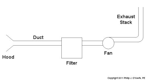
Figure 1 – Local Exhaust Ventilation System With Cyclone
Here’s how it works. A local exhaust ventilation system draws in corrupted air by means of a strategically placed hood, and its fan pulls the captured air and dust mixture through ductwork and into the cyclone. The cyclone is shaped like a cone standing upright on its small end. A cutaway view is shown in Figure 2.

Figure 2 – Cutaway View of a Cyclone
When a quickly-moving air and dust mixture gets drawn into the cyclone by the fan, the mixture is forced to spiral down into the cone by the shape of the inlet passage. Because dust particles are heavier than air molecules, they tend to separate due to centrifugal force. The heavier dust particles are sent crashing into the sloping sides of the cone. They then slide down to the bottom of the cone, where they will eventually fall through the bottom and into a waiting trash bin. The lighter air tends to stay in the center of the cyclone and is eventually drawn out by the fan through the outlet passage.
Unfortunately, cyclones are not 100% efficient when it comes to removing dust from the air. Their efficiency depends on many factors, including the shape of the cyclone, the speed of the flow going through it, and the weight of the dust particles. In any case, there’s always going to be some dust that will escape along with the air that’s being exhausted to the building’s exterior through the exhaust stack. If necessary, this air can be cleaned further before being released into the atmosphere by the use of additional filtration located within the ductwork between the cyclone and the fan.
That wraps up our discussion on dust removal through mechanical filtration. Next time we’ll look at systems capable of removing chemical vapors.
_____________________________________________
|
Tags: blower, centrifugal force, cone, cyclone, cyclone separator, duct, ductwork, dust, dust particles, engineering expert witness, exhaust stack, fan, filter, forensic engineer, hood, local exhaust ventilation system, spiral, vacuum
Posted in Engineering and Science, Innovation and Intellectual Property, Personal Injury | Comments Off on Industrial Ventilation – Local Exhaust Ventilation Filters and Air Cleaners II


