Posts Tagged ‘pressure’
Monday, April 16th, 2018
|
Ever hear the old saying, “There’s more than one way to cook a goose”? The statement is meant to encourage creative thinking when problem solving. This forward thinking can be applied to the problem of destructive cavitation bubbles as well. Finding ways to reduce cavitation is something engineers are well versed in. As discussed in our last blog, one way to prevent cavitation is by lowering water temperature at a centrifugal pump’s inlet. But sometimes that isn’t possible. Today we’ll discuss another way, reducing cavitation by increasing water pressure.
One way to Reduce Cavitation by Increasing Water Pressure
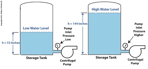
If you’ve ever seen a movie featuring divers, you’ll no doubt be aware that the deeper a diver goes, the more water pressure there is bearing down on him from above. The same goes for a centrifugal pump’s storage tank. The higher the water level inside the tank, the higher the pressure bearing down on the pump’s inlet, which is located at the bottom of the tank. This is the area in which cavitation bubbles are likely to form. The mathematical equation that illustrates this relationship is,
P = γ × h (1)
where, P is water pressure at the bottom of the tank, γ is the Greek symbol gamma, representing the specific weight of water, (0.036 pounds/inch3), and h is the depth of the water inside the tank.
Let’s see what happens when we increase the water level, h, from 72 inches, shown on the left, to 144 inches, on the right.
P = (0.036 Lb/in3) × (72 in) = 2.592 PSI (2)
When the water level is raised to 144 inches, P becomes,
P = (0.036 Lb/in3) × (144 in) = 5.184 PSI (3)
We see that by raising the water level in the tank from 72 to 144 inches, pressure at the bottom of the tank where the inlet is located is increased from 2.592 PSI to 5.184 PSI, pounds per square inch.
Next time we’ll see how simply elevating the tank has an impact on cavitation.
Copyright 2018 – Philip J. O’Keefe, PE
Engineering Expert Witness Blog
____________________________________ |
Tags: cavitation, cavitation bubbles, centrifugal pump, engineering, pressure, pump inlet, specific weight of water, storage tank, temperature, water level
Posted in Engineering and Science, Expert Witness, Forensic Engineering, Innovation and Intellectual Property, Personal Injury, power plant training, Product Liability | Comments Off on One way to Reduce Cavitation by Increasing Water Pressure
Monday, April 9th, 2018
|
As we learned previously, cavitation bubbles form at a centrifugal pump’s inlet when the thermodynamic properties of water, namely temperature and pressure, are right. Today we’ll see how just manipulating water temperature can control cavitation.

Manipulating Water Temperature to Control Cavitation
Some centrifugal pumps draw water from an external heat source such as a heat exchanger in order to provide heat to buildings, generate power, and perform manufacturing processes. On some exchangers heat is applied at a fixed rate and can’t be varied. On others heat can be varied by using a heat exchanger fitted with a temperature control. This makes it easy to reduce or lower water temperature introduced at the pump’s inlet. If the temperature is kept low enough relative to the pressure at the inlet, cavitation bubbles won’t form.
Let’s say water enters the pump’s inlet from a heat exchanger at 59ºF and internal pump pressure is 0.25 pounds per square inch (PSI). With these parameters in place water boils and cavitation bubbles will form in the pump inlet. But if the heat exchanger is adjusted so that temperature is lowered by a mere two degrees to 57ºF, cavitation ceases. This is in accordance with the boiling points of water, listed for various pressures and temperatures, as published in engineering thermodynamic texts.
If it’s not possible to lower water temperature at the pump inlet, an alternate method to control cavitation is to raise water pressure, which can be accomplished in different ways. We’ll review those options next time.
Copyright 2018 – Philip J. O’Keefe, PE
Engineering Expert Witness Blog
____________________________________ |
Tags: cavitation, centrifugal pump, engineering, heat exchanger, pressure, temperature, temperature control, thermodynamics
Posted in Engineering and Science, Expert Witness, Forensic Engineering, Innovation and Intellectual Property, Personal Injury, power plant training, Product Liability | Comments Off on Manipulating Water Temperature to Control Cavitation
Tuesday, November 26th, 2013
|
Last time we learned that the amount of useful work, W, that a steam turbine performs is calculated by taking the difference between the enthalpy of the steam entering and then leaving the turbine. And in an earlier blog we learned that a vacuum is created in the condenser when condensate is formed. This vacuum acts to lower the pressure of turbine exhaust, and in so doing also lowers the enthalpy of the exhaust steam. Putting these facts together we are able to generate data which demonstrates how the condenser increases the amount of work produced by the turbine.
To better gauge the effects of a condenser, let’s look at the differences between its being present and not present. Let’s first take a look at how much work is produced by a steam turbine without a condenser.

The steam entering the turbine inlet has a pressure of 2000 pounds per square inch (PSI) and a temperature of 1000°F. Knowing these turbine inlet conditions, we can go to the steam tables in any thermodynamics book to find the enthalpy, h1. Titles such as Fundamentals of Classical Thermodynamics by Gordon J. Van Wylen and Richard E. Sonntag list enthalpy values over a wide range of temperatures and pressures. For our example this volume tells us that,
h1 = 1474 BTU/lb
where BTU stands for British Thermal Units, a unit of measurement used to quantify the energy contained within steam or water, in our case the water to steam cycle inside a power plant. Technically speaking, a BTU is the amount of heat energy required to raise the temperature of one pound of water by one degree Fahrenheit. The term lb should be a familiar one, it’s the standard abbreviation used for pound, so enthalpy is the measurement of the amount of energy per pound of steam flowing through, in this case, the turbine.
Since there is no condenser attached to the steam turbine’s exhaust in our illustration, the turbine discharges its spent steam into the surrounding atmosphere. The atmosphere in our scenario exists at 14.7 PSI because our power plant happens to be at sea level. Knowing these facts, the steam tables inform us that the value of the exhausted steam’s enthalpy, h2, is:
h2 = 1015 BTU/lb
Combining the two equations we are able to calculate the useful work the turbine is able to perform as:
W = h1 – h2 = 1474 BTU/lb – 1015 BTU/lb = 459 BTU/lb
This equation tells us that for every pound of steam flowing through it, the turbine converts 459 BTUs of the steam’s heat energy into mechanical energy to run the electrical generator.
Next week we’ll connect a condenser to the steam turbine to see how its efficiency can be improved.
________________________________________
|
Tags: British Thermal Unit, BTU, coal power plant expert, condensate, condenser, engineering expert witness, enthalpy, power engineer, power plant training seminar, pressure, steam, steam power plant, steam tables, steam turbine, steam turbine engineering expert witness, thermodynamics, turbine exhaust steam, vacuum, water, work
Posted in Engineering and Science, Expert Witness, Forensic Engineering, Innovation and Intellectual Property, Personal Injury, power plant training, Product Liability | Comments Off on Enthalpy Values in the Absence of a Condenser
Thursday, November 14th, 2013
|
Last time we learned how the formation of condensate within a power plant’s turbine results in a vacuum being created. This vacuum plays a key role in increasing steam turbine efficiency because it affects a property known as enthalpy, a term used to denote total heat energy contained within a substance. For the purposes of our discussion, that would be the heat energy contained within steam which flows through the turbine in a power plant.
The term enthalpy was first introduced by scientists within the context of the science of thermodynamics sometime in the early 20th Century. As discussed in a previous blog article, thermodynamics is the science that deals with heat and work present within processes. Enthalpy is a key factor in thermodynamics, and is commonly represented in engineering calculations by the letter h and denoted as,
h = u + Pv
where u is the internal energy of a substance, let’s say steam; P is the pressure acting upon a specific volume, v, of the steam; and P and v are multiplied together. Pressure is force per unit area and is measured in psi, pounds per square inch. For the purposes of our discussion, it’s the amount of pressure that steam places on pipes containing it.
Looking at the equation above, simple math tells us that if we increase the pressure, P, the result will be an increase in enthalpy h. If we decrease P, the result will be a decrease in h. Now, let’s see why this property is important with regard to the operation of a steam turbine.
When it comes to steam turbines, thermodynamics tells us that the amount of work they perform is proportional to the difference between the enthalpy of the steam entering the turbine and the enthalpy of the steam at the turbine’s exhaust. What is meant by work is the act of driving the electrical generator, which in turn provides electric power. In other words, the work leads to a useful outcome. This relationship is represented by the following equation,
W = h1 – h2
In terms of the illustration below, W stands for work, or potential for useful outcome of the turbine/generator process in the form of electricity, h1 is the enthalpy of the steam entering the inlet of the turbine from the superheater, and h2 is the enthalpy of the steam leaving at the turbine exhaust.

We’ll discuss the importance of enthalpy in more detail next week, when we’ll apply the concept to the work output of a steam turbine.
________________________________________
|
Tags: boiler, coal power plant, condensate, condenser, electrical generator, engineering expert witness, enthalpy difference, forensic engineer, heat energy, internal energy of steam, pipes, power plant design, power plant engineering expert, power plant operation, power plant training, pressure, specific volume of steam, steam pressure, steam turbine, steam turbine work, steam water cycle, superheater, thermodynamics, useful work, vacuum
Posted in Engineering and Science, Expert Witness, Forensic Engineering, Innovation and Intellectual Property, Personal Injury, power plant training, Product Liability | Comments Off on Enthalpy and Steam Turbines
Monday, July 29th, 2013
|
Last time we discovered that the boiling point of water varies. It’s dependent upon the amount of pressure exerted on its surface, which varies due to a variety of reasons, including where it is in relation to sea level. Before we see what happens under higher than atmospheric pressures, such as exist in an electric utility power plant boiler, let’s cover some basics.
In the power plant, water is heated in a boiler specifically to produce steam, unlike our tea kettle where the primary purpose is to produce hot water. The steam produced is used to spin turbine generators, which in turn generate electricity, as I explained in a previous blog on steam turbines.
Unlike a tea kettle, which is open to the atmosphere on your kitchen stove, the boiler in a power plant is an enclosed, reinforced steel vessel. See illustration below.

The reinforced steel boiler vessel is designed to withstand great internal pressure as temperatures rise within. In addition to providing a safety feature, the enclosed space provides a sheltered environment for collecting steam so it can later be put to use spinning power generating turbines down the line. In other words, surface water inside the boiler is closed off from the surrounding atmosphere, allowing its internal pressure to build for our specific purposes.
As heat energy is added to water within the boiler, the water boils and steam bubbles break out from its surface, filling the empty space above the surface with pressurized steam. This steam will try to expand here, but it can’t, because it’s being constrained by the reinforced steel vessel within which it is enclosed. Instead, steam pressure builds up on the surface of the water inside the boiler until it is high enough to be released through an attached pipe which is connected to a nearby turbine.
We’ll talk more about this pent-up energy and how it is put to use within the power plant in next week’s blog.
___________________________________________
|
Tags: boiler, boiler water, boiling point, coal, coal power plant, electric utility power plant, engineering expert witness, forensic engineer, heat energy, power plant engineer, pressure, steam turbine, turbine, water
Posted in Engineering and Science, Expert Witness, Forensic Engineering, Innovation and Intellectual Property, Personal Injury, power plant training | Comments Off on Heat Energy Within the Power Plant—The Power Behind the Turbines
Sunday, July 21st, 2013
|
If you’ve ever baked from a pre-packaged cake or cookie mix, you’ve probably noticed the warning that baking times will vary. That’s because the elevation of the area in which you’re doing the baking makes a difference in the baking time required. Living in New Orleans? Then you’re at or below sea level. In Colorado? Then you’re above sea level. Your cake will be in the oven more or less time at the prescribed temp, depending on your location.
Last time we learned how the heat energy absorbed by water determines whether it exists in one of the three states of matter, gas, liquid, or solid. We also learned that at the atmospheric pressure present at sea level, which is about 14.7 pounds per square inch (PSI), the boiling point of water is 212°F. At sea level there are 14.7 pounds of air pressure bearing down on every square inch of water surface. Again, I said sea level for a reason.
The boiling point of water, just like cake batter baking times, is dependent upon the amount of pressure that’s being exerted on its surface from the surrounding atmosphere. When heat energy is absorbed, it causes the water or cake batter molecules to move around. In fact, the temperature measured is a reflection of this molecular movement. As more heat energy is absorbed, the molecules move more and more rapidly, causing temperature to increase.
When the water temperature in our tea kettle reaches its boiling point of 212°F at sea level, the steam molecules in the bubbles that form have enough energy to overcome the atmospheric pressure on the surface of the water. They become airborne and escape in the form of steam.

If we’re up in the Rockies at say an altitude of 7000 feet above sea level, the atmospheric pressure is only about 10.8 PSI. There’s just less air up there. That means there’s less air pressure resting upon the surface of the water, so it’s far easier for steam molecules to form into bubbles and leave the surface. As a result the boiling point is much lower in the Rockies than it is at sea level, 196°F versus 212°F.

So what if the water was boiling in an environment that had even higher pressures exerted upon it than just atmospheric? We’ll see how to put this pent-up energy to good use next week, when we begin our discussion on how steam is used within electric utility power plants.
___________________________________________
|
Tags: air pressure, atmosphere, atmospheric pressure, boiler, boiler engineer, boiling point, boiling point of water, boiling water, electric utility power plant, engineering expert witness, forensic engineer, heat energy, molecules, pounds per square inch, pressure, PSI, steam, steam bubbles, water
Posted in Engineering and Science, Expert Witness, Forensic Engineering, Innovation and Intellectual Property, Personal Injury, power plant training, Product Liability, Professional Malpractice | Comments Off on Forms of Heat Energy – Boiling Water and Atmospheric Pressure
Sunday, February 20th, 2011
|
When I was a kid I didn’t have video games or cable TV to help me occupy my time. Back then parents tended to be frugal, and the few games I had were cheap to buy and simple in operation, like the plastic toy windmill I’d play with for hours on end. All I had to do to make it spin was take a deep breath, pucker my lips together, fill my cheeks with breath, then blow hard into the windmill blades. Its spin was fascinating to watch. Little did I know that as an adult I would come to work with a much larger and complex version of it, in the form of a power plant’s steam turbine.
You see, when you trap breath within bulging cheeks and then squeeze your cheek muscles together, you actually create a pressurized environment. This air pressure buildup transfers energy from your mouth muscles into the trapped breath within your mouth, so that when you open your lips to release the breath through your puckered lips, the pressurized energy is converted into kinetic energy, a/k/a the energy of movement. The breath molecules flow at high speed from your lips to the toy windmill’s blades, and as they come into contact with the blades their energy is transferred to them, causing the blades to move. A similar process takes place in the coal power plant, where steam from a boiler takes the place of pressurized breath and a steam turbine takes the place of the toy windmill.
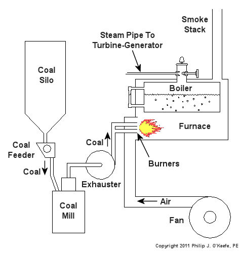
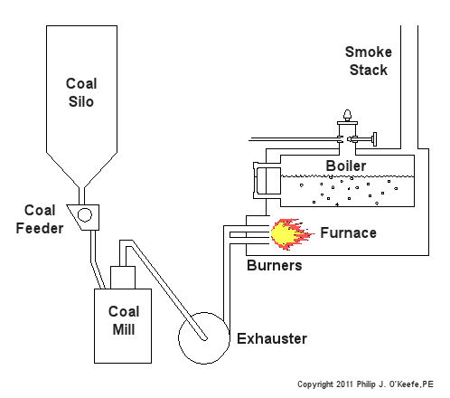
If you recall from my previous article, the heat energy released by burning coal is transferred to water in the boiler, turning it to steam. This steam leaves the boiler under great pressure, causing it to travel through pipe to the steam turbine, as shown in Figure 1.

Figure 1 – A Basic Steam Turbine and Generator In A Coal Fired Power Plant
At its most basic level the inside of a steam turbine looks much like our toy windmill, of course on a much larger scale, and it is very appropriately called a “wheel.” See Figure 2.

Figure 2 – A Very Basic Steam Turbine Wheel
The wheel is mounted on a shaft and has numerous blades. It makes use of the pressurized steam that has made its way to it from the boiler. This steam has ultimately passed through a nozzle in the turbine that is directed towards the blades on the wheel. This is the point at which heat energy in the steam is converted into kinetic energy. The steam shoots out of the nozzle at high speed, coming into contact with the blades and transferring energy to them, which causes the turbine shaft to spin. The turbine shaft is connected to a generator, so the generator spins as well. Finally, the spinning generator converts the mechanical energy from the turbine into electrical energy.
In actuality, most coal power plant steam turbines have more than one wheel and there are many nozzles. The blades are also more numerous and complex in shape in order to maximize the energy transfer from the steam to the wheels. My Coal Power Plant Fundamentals seminar goes into far greater detail on this and other aspects of steam turbines, but what I have shared with you above will give you a basic understanding of how they operate.
So to sum it all up, the steam turbine’s job is to convert the heat energy of steam into mechanical energy capable of spinning the electrical generator. Next time we’ll see how the generator works to complete the last step in the energy conversion process, that is, conversion of mechanical energy into electrical energy.
_____________________________________________ |
Tags: boiler, coal power plant training, electric utility training, electrical generator, engineering expet witness, forensic engineering, fossil fuel, generating station, heat energy, high pressure steam, kinetic energy, nozzle, power engineering, pressure, seminar, steam, steam pipe, steam turbine, turbine blade, turbine generator, windmill
Posted in Engineering and Science, Personal Injury, power plant training | 5 Comments »


