Archive for July, 2012
Sunday, July 29th, 2012
| I joined the Boy Scouts of America as a high schooler, mainly so I could participate in their Explorer Scout program and learn about electronics. I will forever be grateful to the Western Electric engineers who volunteered their personal time to stay after work and help me and my fellow Scouts build electronic projects. The neatest part of the whole experience was when I built my first regulated power supply with their assistance inside their lab. But in order to appreciate the beauty of a regulated power supply we must first understand the shortcomings of an unregulated one, which we’ll begin to do here.
Last time we began to discuss how the output voltage of an unregulated power supply can vary in response to power demand, just as when sprinklers don’t have sufficient water flow to cover a section of lawn. Let’s explore this concept further.
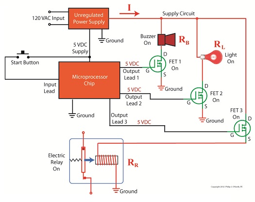
Figure 1
Figure 1 shows a very basic representation of a microprocessor control system that operates three components, an electric relay (shown in the blue box), buzzer, and light. These three components have a certain degree of internal electrical resistance, annotated as RR, RB, and RL respectively. This is because they are made of materials with inherent imperfections which tend to resist the flow of electric current. Imperfections such as these are unavoidable in any electronic device made by humans, due to impurities within metals and irregularities in molecular structure. When the three components are activated by the microprocessor chip via field effect transistors, denoted as FET 1, 2 and 3 in the diagram, their resistances are connected to the supply circuit.
In other words, RR, RB, and RL create a combined level of resistance in the supply circuit by their connectivity to it. If a single component were to be removed from the circuit, its internal resistance would also be removed, resulting in a commensurate decrease in total resistance. The greater the total resistance, the more restriction there is to current flow, denoted as I. The greater the resistance, the more I is caused to decrease. In contrast, if there is less total resistance, I increases.
The result of changing current flow resistance is that it causes the unregulated power supply output voltage to change. This is all due to an interesting phenomenon known as Ohm’s Law, represented as this within engineering circles:
V = I × R
where, V is the voltage supplied to a circuit, I is the electrical current flowing through the circuit, and R is the total electrical resistance of the circuit. So, according to Ohm’s Law, when I and R change, then V changes.
Next time we’ll apply Ohm’s Law to a simplified unregulated power supply circuit schematic. In so doing we’ll discover the mathematical explanation to the change in current flow and accompanying change in power supply output voltage we’ve been discussing.
____________________________________________ |
Tags: buzzer, current flow, electric current, electric relay, electrical component, electrical engineers, electronic device, electronic projects, electronics, engineering expert witness, FET, field effect transistor, forensic engineer, internal resistance, light, microprocessor chip, microprocessor control, Ohm's Law, output voltage varies, power supply, regulated power supply, resistance, schematic, supply circuit, unregulated power supply, voltage
Posted in Engineering and Science, Expert Witness, Forensic Engineering, Innovation and Intellectual Property, Personal Injury, Product Liability | 1 Comment »
Sunday, July 22nd, 2012
Electrical voltage flow and water flow have a lot in common. They’re both affected by fluctuations in supply, fluctuations which can adversely impact both performance and equipment integrity. Take for example a sprinkler that fails to cover a designated section of lawn due to heavy neighborhood demand. Everybody wants to water on the weekend when it’s been 90 degrees all week, and low water pressure is the result. There are times when it’s hard to get a glass of water. By contrast in the winter months, when water demands tend to be lower, water supplies are plentiful. This scenario of varying water pressure is analogous to what sometimes occurs within electric circuits.
In my previous blog article on wall warts, I described the operation of a simple power supply consisting of a transformer, diode bridge, and capacitor. Together, these components converted 120 volts alternating current (VAC) to 12 volts direct current (VDC). The wall wart power supply is fine for many applications, however it is unregulated, meaning if there are any sudden surges in power, such as spikes or dips caused by lightning strikes or other disturbances on the electric utility system, there could be problems.
Take for example a power supply that is used in conjunction with sensitive digital logic chips, like the one used in my x-ray film processor design shown in my last blog article. These chips are designed to run optimally on a constant voltage, like 5 VDC, and when that doesn’t happen input signals can fail to register with the computer program and cause a variety of problems, such as output signals turning on and off at will. In the film processor the drive motor may start at the wrong time or get stuck in an on modality. If power surges are high enough, microprocessor chips can get damaged, compromising the entire working unit.
The output voltage of an unregulated power supply can also vary in response to power demand, just as when sprinklers don’t have sufficient water flow to cover a section of lawn. Demand for power can change within a circuit when electrical components like relays, lights, and buzzers are turned on and off by digital logic chips.
Next time we’ll take a look at a basic concept of electrical engineering known as “Ohm’s Law” and how it governs the variable output voltage response of unregulated power supplies.
____________________________________________
|
Tags: alternating current, buzzer, capacitor, damage, demand for power, digital logic chip, diode bridge, direct current, disturbances, drive motor, electric relay, electric utility system, electrical components, electronics, engineering expert witness, forensic engineer, input signal, lightning strike, microprocessor chip, Ohm's Law, output signal, power supply, power surge, transformer, turn on and off, unregulated power supply, voltage regulation, wall wart
Posted in Engineering and Science, Expert Witness, Forensic Engineering, Innovation and Intellectual Property | Comments Off on Transistors – Voltage Regulation
Sunday, July 15th, 2012
| Last time we looked at my electric relay solution to a problem presented by a 120 volt alternating current (VAC) drive motor operating within an x-ray film processing machine. Now let’s see what happens when we press the button to set the microprocessor into operation.
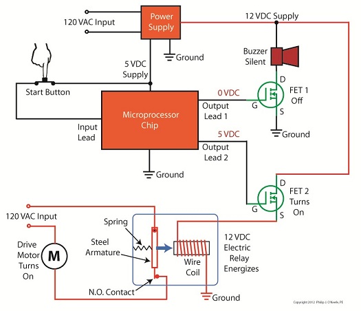
Figure 1
Figure 1 shows that when the button is depressed, the computer program contained within the microprocessor chip goes into action, signaling the start of the control initiative. 5 volts direct current (VDC) is supplied to Output Lead 2, and FET 2 (Field Effect Transistor 2) becomes activated, which allows electric current from the 12 VDC supply to course into the 12 VDC electric relay, through the relay’s wire coil, then conclude its travel into electrical ground.
The electric relay components, including a wire coil, steel armature, spring, and normally open (N.O.) contact, are shown within a blue box in our illustration. Current flow is represented by red lines. The control initiative passes from the microprocessor to FET 2, and then to the 12 VDC electric relay, just as the Olympic Torch is relayed through a system of runners.
We learned in one of my previous articles on industrial control that when an electric relay coil is energized, electromagnetic attraction pulls its steel armature towards the wire coil and the N.O. electrical contact. In Figure 1 this attraction is represented by a blue arrow. With the N.O. contact closed the drive motor is connected to the 120 VAC input, and the motor is activated.
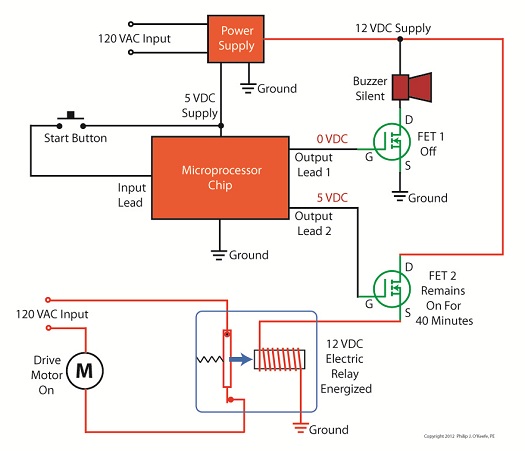
Figure 2
Figure 2 shows what happens after the button is depressed. The computer program is activated, directing the microprocessor chip to keep 5 VDC on Output Lead 2 and FET 2 while the prerequisite 40 minutes elapses. Thus the relay remains energized and the motor remains on during this time.
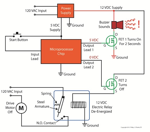
Figure 3
In Figure 3, at the end of the 40 minute countdown, the computer program applies 0 VDC to Output Lead 2. FET 2 then turns off the current flow to the relay and it begins to de-energize, causing the spring to pull the steel armature away from the N.O. contact and the 120 VAC power supply to be interrupted. The motor is deactivated.
At the same time, the computer program applies 5 VDC to Output Lead 1 and FET 1 for 2 seconds. FET 1 turns on the flow of current through the buzzer, causing it to sound off and signal that the x-ray film processing machine is ready for use.
Next time we’ll look at how transistors are used to regulate voltage within direct current power supplies like the one shown in Figure 3 above.
____________________________________________ |
Tags: armature, buzzer, computer program, design, electric circuit, electric drive motor, electric relay, electronic control, electronics, engineering expert witness, FET, field effect transistor, forensic engineer, industrial control, machine, microprocessor chip, microprocessor control, MOSFET, motor control, normally open contact, output lead, power supply, pushbutton, spring, transistor, voltage regulator, wire coil, x-ray film processing machine
Posted in Engineering and Science, Expert Witness, Forensic Engineering, Innovation and Intellectual Property, Personal Injury, Product Liability | Comments Off on Transistors – Digital Control Interface, Part V
Monday, July 9th, 2012
| The Olympic Torch relay, soon to culminate in London, is the grand daddy of all relays, starting in one country, traversing many others, then ending its journey at the site of the Olympic Games. It passes through many athletes’ hands while on its journey, its final purpose being to light the Olympic Flame. Less glamorous, though still useful, is the relay race that often takes place within digital controls.
Last time we looked at my design solution for the control of a microprocessor controlled medical x-ray film developing machine, where a field effect transistor (FET) acted as a digital control interface between a 5 volt direct current (VDC) microprocessor and a 12 VDC buzzer. Well, controlling the buzzer wasn’t the only function of the microprocessor. It also had to control a 120 volt alternating current (VAC) drive motor, the purpose of which was to move x-ray film through a series of processes within the machine. Yet another requirement was that the machine’s drive motor run 40 minutes upon activation by a start button, then shut off.
One of the challenges presented by this specification was that an FET standing alone is only suited to control direct current devices like the buzzer, but not alternating current devices like electric motors. Direct current flows in one direction only when traveling through wire, and since an FET can only pass current in one direction it is the perfect match for those applications.
Now, as the name would imply, alternating current flow alternates, that is, it reverses direction and varies in intensity many times each second. This is a scenario that FETs are not equipped to handle because they can’t deal with reverse flow. This meant that, for the purpose of my developing machine, I could not use an FET to directly control the 120 VAC motor. Now let’s take a look at Figure 1 to get a basic look at how I solved the problem.
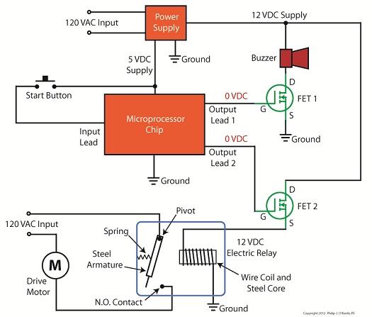
Figure 1
Figure 1 shows not one, but two green FET’s, each branching off from the microprocessor chip. We’ll call them FET 1 and FET 2. If you recall from last time, the buzzer works on 12 VDC, so FET 1 works well as a direct interface between it and the microprocessor chip. But in the case of FET 2 we need an intermediary device to handle the alternating current motor. That device is a 12 VDC electric relay.
In an earlier blog series on industrial controls I discussed how electric relays use electromagnets to power light bulbs and motors on and off in response to someone pressing a button on a control panel. We have very much the same mechanics at play in our developing machine. The relay will power the motor on and off in response to the computer program running within the 5 VDC microprocessor, a programming sequence that is initiated by someone pressing a button.
To get the motor control to work in the machine, the gate (G) of FET 2 is connected to another output lead on the microprocessor. We’ll call that Output Lead 2. Then, the source (S) of FET 2 is connected to the wire coil in the relay. To tap into the power source for the relay, the drain (D) of FET 2 is connected to the 12 VDC supply. Finally, the other end of the relay coil is connected to electrical ground.
Next time we’ll activate the pushbutton and see how the control initiative passes along a path in a manner reminiscent of the flame in an Olympic Torch relay, but here it passes between the microprocessor, the FET and electrical relay, culminating in power to the drive motor.
____________________________________________ |
Tags: 12 VDC, 120 VAC, alternating current, digital control, digital control interface, digital input, digital output, direct current, drain, drive motor, electric current, electric motor control, electric motors, electric relay, electrical ground, electronic device, engineering expert witness, FET, field effect transistor, forensic engineer, gate, machine control, microprocessor, microprocessor chip, output lead, pushbutton, relay coil, source, start button, transistor, x-ray film machine
Posted in Engineering and Science, Expert Witness, Forensic Engineering, Innovation and Intellectual Property, Personal Injury, Product Liability | 1 Comment »
Sunday, July 1st, 2012
| When I was in engineering school in the mid 1970s microprocessor chips were still a fairly new concept. Scientific calculators were the size of a brick back then, and they weighed almost as much, and there were no personal computers.
I remember doing homework on the UNIVAC 1108 mainframe computer at school. To program it I had to sit at a monster of a keypunching machine for which I punched an endless array of holes into paper cards. These holes acted as the programming logic to instruct the computer what functions to perform. The 1108 computer’s mainframe was so huge it was housed in an adjoining room the size of a house. Since the 1980s advances in microprocessor technology have increased computing power and dramatically reduced the size of components, making things like laptops, smart phones, and sophisticated electronic products possible.
Last time we began looking at my design solution for the control of a machine which developed medical x-ray film and made use of a microprocessor chip to automate its operation. A field effect transistor (FET) acts as a digital control interface between its 5 volt direct current (VDC) microprocessor and a 12 VDC buzzer. Figure 1 shows what happens when someone presses the button to put everything into action and the microprocessor starts timing.
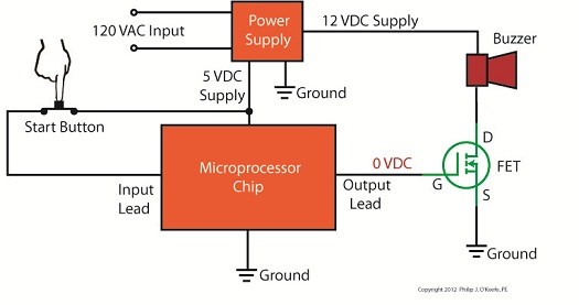
Figure 1
With the button depressed the chip senses 5 VDC from the power supply on its input lead. This in turn signals the computer program to turn the product on. The program then begins counting down the minutes, all the while maintaining a 0 voltage output from the chip’s output lead. With no voltage present on its G lead, the FET does not permit electrical current to flow from the 12 VDC supply, through the buzzer, through D and S, and down to electrical ground. The buzzer remains silent.
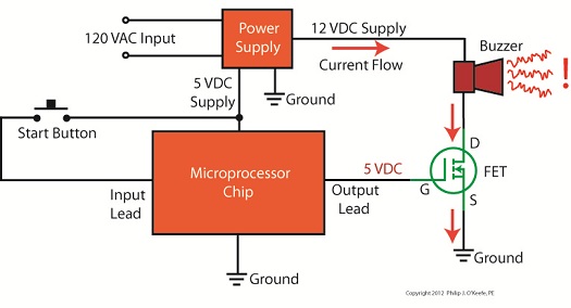
Figure 2
Figure 2 shows what happens when the program begins its 40-minute warming sequence. The chip raises the output lead voltage to 5 VDC and applies it to G, then the FET permits electric current to flow through it to ground from the 12 VDC supply and the buzzer. Now supplied with power, the buzzer sounds. Then, per programming instructions, after 2 seconds the program shuts off the voltage in the chip’s output lead, current is cut off, and the buzzer goes silent.
Next time we’ll see how an FET can be used as an interface between a microprocessor and another higher powered device, that of a 120 VAC motor that’s used to move x-ray film through a series of processes within the developer.
____________________________________________
|
Tags: 12 VDC, 5 VDC, alarm, automate, buzzer, current, D, design solution, digital control, electric relay, electrical design, electronics, engineering expert witness, FET, field effect transistor, forensic engineer, G, hardware design, machine control, medical product, microprocessor chip, MOSFET, motor, power supply, programming logic, pushbutton, S, voltage
Posted in Engineering and Science, Expert Witness, Forensic Engineering, Innovation and Intellectual Property, Personal Injury, Product Liability | Comments Off on Transistors – Digital Control Interface, Part III


