| Through the ages it’s been common practice to name important discoveries after those who discovered them. For example, James Watt was a mechanical engineer who improved the steam engine by finding a solution to the problem of steam condensing into water inside the engine, a phenomenon which resulted in the engine cooling and reducing its efficiency. Thus it was fitting that a metric unit of power, the watt, was named in his honor. Today we’ll become acquainted with the man behind the naming of the Zener diode, Clarence Zener, and take a look at his contributions with regard to the function of this electrical component.
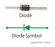
Last time we began our discussion on electrical components known as diodes and saw how they’re used on circuit paths to govern the flow of current. The Zener diode is a particular type of diode and a key component in transistorized voltage regulator circuits, as we’ll see later. For now, let’s see how it works. The symbol for the Zener diode is almost identical to that of a standard diode, introduced in my previous blog, but the Zener version has a bent line going through it resembling a distorted letter “z.” See Figure 1.
Figure 1
Electric current flows through the Zener Diode just as it does through a standard diode. But when the current flows in reverse, that’s where the similarity ends. See Figure 2. Figure 2
When current tries to flow in the reverse direction, the Zener diode acts as an electrical conductor and allows current to pass through it. In other words, it doesn’t block current flow as standard diodes do. At this point, you may be asking, “What’s so special about that?” Perhaps you’ve made the connection that it behaves no differently than a metal wire. But that isn’t entirely correct. You see, when current passes in the reverse direction through the Zener diode, it maintains a constant voltage. This is called the Zener Voltage and is denoted as VZener. The significance here is that within the circuit, any electronic component connected across the leads of a Zener diode will be supplied with a constant, unchanging voltage. Thus the Zener diode works as a voltage regulator, enabling devices connected to it to have smooth, uninterrupted operation at a constant voltage. It should be noted that this phenomenon only happens when the current flowing through the Zener diode is flowing in reverse. Next time we’ll look at a basic regulated power supply circuit to see how a Zener diode is incorporated in order to maintain a consistent output voltage. ____________________________________________ |
Posts Tagged ‘electrical components’
Transistors – Voltage Regulation Part X
Monday, September 24th, 2012

Transistors – Voltage Regulation Part V
Sunday, August 19th, 2012| I’m sure you’ve seen the television commercials warning about harmful interactions between prescription medications. By the same token electronic circuitry can also be adversely affected by certain combinations of electrical components, as we’ll discuss in today’s blog.
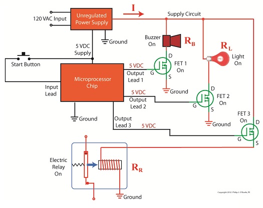
Last time we looked at a circuit schematic containing an unregulated power supply. This power supply was connected to an external supply circuit containing a number of components such as electric relays, buzzers, and lights. Each of these components has a resistance factor, and combined they have a total resistance of RTotal. We saw that when RTotal increases, the electrical current, I, decreases, and when RTotal decreases, I increases. In contrast to this increasing/decreasing activity of the total resistance RTotal, the fixed internal resistance of the unregulated power supply, RInternal, doesn’t fluctuate. Let’s explore Ohm’s Law further to see how the static effect of RInternal combines with the changing resistance present in RTotal to adversely affect the unregulated power supply output voltage, VOutput, causing it to fluctuate.
Figure 1
In Figure 1 RTotal and RInternal are operating in series, meaning they are connected together like sausage links. In this configuration their two resistances add together as if they were one larger resistor. Generally speaking, Ohm’s Law sets out that the current, I, flowing through a resistor in an electrical circuit equals the voltage, V, applied to the resistor divided by the resistance R, or: I = V ÷ R In the case of the circuit represented in Figure 1, the resistors RInternal and RTotal are connected in series within the circuit, so their resistances must be added together to arrive at a total power demand. Voltage is applied to these two resistors by the same voltage source, VDC. So, for the circuit as a whole Ohm’s Law would be written as: I = VDC ÷ (RInternal + RTotal) But, Ohm’s Law can also be applied to individual parts within the circuit, just as it can be applied to a single kitchen appliance being operated on a circuit shared with other appliances. Let’s see how this applies to our example circuit’s RTotal next week. ____________________________________________ |

Transistors – Voltage Regulation
Sunday, July 22nd, 2012| Electrical voltage flow and water flow have a lot in common. They’re both affected by fluctuations in supply, fluctuations which can adversely impact both performance and equipment integrity. Take for example a sprinkler that fails to cover a designated section of lawn due to heavy neighborhood demand. Everybody wants to water on the weekend when it’s been 90 degrees all week, and low water pressure is the result. There are times when it’s hard to get a glass of water. By contrast in the winter months, when water demands tend to be lower, water supplies are plentiful. This scenario of varying water pressure is analogous to what sometimes occurs within electric circuits.
In my previous blog article on wall warts, I described the operation of a simple power supply consisting of a transformer, diode bridge, and capacitor. Together, these components converted 120 volts alternating current (VAC) to 12 volts direct current (VDC). The wall wart power supply is fine for many applications, however it is unregulated, meaning if there are any sudden surges in power, such as spikes or dips caused by lightning strikes or other disturbances on the electric utility system, there could be problems.
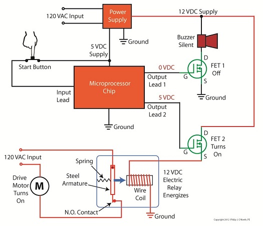
Take for example a power supply that is used in conjunction with sensitive digital logic chips, like the one used in my x-ray film processor design shown in my last blog article. These chips are designed to run optimally on a constant voltage, like 5 VDC, and when that doesn’t happen input signals can fail to register with the computer program and cause a variety of problems, such as output signals turning on and off at will. In the film processor the drive motor may start at the wrong time or get stuck in an on modality. If power surges are high enough, microprocessor chips can get damaged, compromising the entire working unit. The output voltage of an unregulated power supply can also vary in response to power demand, just as when sprinklers don’t have sufficient water flow to cover a section of lawn. Demand for power can change within a circuit when electrical components like relays, lights, and buzzers are turned on and off by digital logic chips. Next time we’ll take a look at a basic concept of electrical engineering known as “Ohm’s Law” and how it governs the variable output voltage response of unregulated power supplies.
____________________________________________ |


