|
Let’s continue our discussion with regard to the example circuit discussed last time and see how the Zener diode works in tandem with the limiting resistor to control current flow and hold the output voltage at a constant level.
Figure 1
To recap our discussion from last week, the unregulated power supply portion of the circuit in Figure 1 generates an unregulated voltage, VUnregulated. Then the Zener diode, which acts as a voltage regulator, takes in VUnregulated and converts it into a steady output voltage, VOutput. Because these output terminals are connected to the ends of the Zener diode, VOutput is equal to the voltage put out by it, denoted as VZener. The Zener diode, an excellent negotiator of current, is essentially involved in a constant trade off, substituting electric current that originates in the unregulated power supply portion of the circuit for voltage, VOutput, that will serve to power the external supply circuit. In other words, the Zener diode draws as much current, IZ, through it as it needs, its objective being to keep VOutput at a constant level, and it will continue to provide this constant output, despite the fact that VUnregulated varies considerably. So, where does the current IZ come from? From IPS, that is, the current flowing from the unregulated power supply area, as shown in Figure 1. IPS flows through the limiting resistor to a junction within the circuit. At this junction, IZ splits off from IPS and continues on to the Zener diode, while current I splits off from IPS on its way to the total internal resistance, RTotal, in the external supply circuit. What this means is that when you add IZ and I together, you get IPS. Mathematically speaking this is represented as: IPS = IZ + I Why solve for IPS? We’ll see why this is important when we revisit Ohm’s Law next week and gain a fuller understanding of how IPS, VUnregulated, VZener, and RLimiting relate to each other with regard to the Zener diode. ____________________________________________ |
Posts Tagged ‘output voltage’
Transistors – Voltage Regulation Part XII
Sunday, October 7th, 2012
Transistors – Voltage Regulation Part XI
Monday, October 1st, 2012|
Without limits on our roadways things would get quickly out of hand. Imagine speeding down an unfamiliar highway and suddenly coming upon a sharp curve. With no speed limit sign to warn you to reduce speed, you could lose control of your car. Limits are useful in many situations, including within electronic circuits to keep them from getting damaged, as we’ll see in a moment.
Last time we introduced the Zener diode and the fact that it performs as a voltage regulator, enabling devices connected to it to have smooth, uninterrupted operation at a constant voltage. Let’s see how it works.
Figure 1
In Figure 1 we have an unregulated power supply circuit introduced in a previous article in this series. We learned that this power supply’s major shortcoming is that its output voltage, VOutput, is unregulated, in other words, it’s not constant. It varies with changes in the direct current supply voltage, VDC. It also varies with changes in, RTotal, which is the total internal resistance of components connected to it. RTotal changes when components are turned on and off by microprocessor and digital logic chips. When VOutput is not constant, those chips can malfunction, causing the device to operate erratically or not at all. But we can easily address this problem by adding a Zener diode voltage regulator between the unregulated power supply and the external supply circuit. See the green portion of Figure 2.
Figure 2
Our power supply now consists of a Zener diode and a limiting resistor, RLimiting. The limiting resistor does as its name implies, it limits the amount of electric current, IZ, flowing through the Zener diode. Without this limiting resistor, IZ could get high enough to damage the diode, resulting in system failure. Next time we’ll see how the Zener diode works in tandem with the limiting resistor to control current flow and hold the output voltage at a constant level. ____________________________________________ |


Transistors – Voltage Regulation Part X
Monday, September 24th, 2012| Through the ages it’s been common practice to name important discoveries after those who discovered them. For example, James Watt was a mechanical engineer who improved the steam engine by finding a solution to the problem of steam condensing into water inside the engine, a phenomenon which resulted in the engine cooling and reducing its efficiency. Thus it was fitting that a metric unit of power, the watt, was named in his honor. Today we’ll become acquainted with the man behind the naming of the Zener diode, Clarence Zener, and take a look at his contributions with regard to the function of this electrical component.
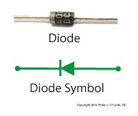
Last time we began our discussion on electrical components known as diodes and saw how they’re used on circuit paths to govern the flow of current. The Zener diode is a particular type of diode and a key component in transistorized voltage regulator circuits, as we’ll see later. For now, let’s see how it works. The symbol for the Zener diode is almost identical to that of a standard diode, introduced in my previous blog, but the Zener version has a bent line going through it resembling a distorted letter “z.” See Figure 1.
Figure 1
Electric current flows through the Zener Diode just as it does through a standard diode. But when the current flows in reverse, that’s where the similarity ends. See Figure 2. Figure 2
When current tries to flow in the reverse direction, the Zener diode acts as an electrical conductor and allows current to pass through it. In other words, it doesn’t block current flow as standard diodes do. At this point, you may be asking, “What’s so special about that?” Perhaps you’ve made the connection that it behaves no differently than a metal wire. But that isn’t entirely correct. You see, when current passes in the reverse direction through the Zener diode, it maintains a constant voltage. This is called the Zener Voltage and is denoted as VZener. The significance here is that within the circuit, any electronic component connected across the leads of a Zener diode will be supplied with a constant, unchanging voltage. Thus the Zener diode works as a voltage regulator, enabling devices connected to it to have smooth, uninterrupted operation at a constant voltage. It should be noted that this phenomenon only happens when the current flowing through the Zener diode is flowing in reverse. Next time we’ll look at a basic regulated power supply circuit to see how a Zener diode is incorporated in order to maintain a consistent output voltage. ____________________________________________ |


Transistors – Voltage Regulation Part VI
Sunday, August 26th, 2012| Believe it or not as a kid in grade school I used to hate math, particularly algebra. None of my teachers were able to decipher its complexities and render it comprehensible to me or the majority of my classmates. Then in high school everything changed. I had Mr. Coleman for freshman algebra, and he had a way of making it both understandable and fun, in a challenging kind of way. With 40 years of teaching under his belt, Mr. Coleman knew exactly how to convey the required information in an understandable manner, and to this day I find his insights useful in solving engineering calculations.
Last time we began our discussion on Ohm’s Law and how it may be applied to our example circuit to solve for the electrical current flowing through it. Let’s continue our discussion to see how the Law applies to only one part of the circuit. Then, we’ll use a little algebra to show how the output voltage of an unregulated power supply is affected by changes in RTotal.
Figure 1
To help us see things more clearly, in Figure 1 we’ll cover up the inside workings of the unregulated power supply side of the circuit and concentrate on the external supply part of the circuit alone. Since RTotal is connected to the terminals of the power supply, the voltage applied to RTotal is the same as the power supply output voltage, VOutput. In my previous article, we learned that according to Ohm’s Law, the current flowing through a resistance is equal to the voltage applied to it, divided by the resistance. The fact that RTotal is connected to the two output terminals like we see in Figure 1, allows us to use Ohm’s law to solve for the electrical current, I, flowing through RTotal: I = VOutput ÷ RTotal Now let’s pull the cover off of the unregulated power supply again to see what’s going on within the circuit as a whole.
Figure 2
In Figure 2 we can see that the current, I, flowing through RTotal is the same current flowing through the balance of the circuit. In the preceding blog we found that value to be: I = VDC ÷ (RInternal + RTotal) We can combine the above two equations for I to develop an algebraic relationship between VOutput and RInternal, RTotal, and VDC: VOutput ÷ RTotal = VDC ÷ (RInternal + RTotal) Then, by rearranging terms and applying the cross multiplication principle of algebra we can solve for VOutput. This involves multiplying both sides of the equation by RTotal: VOutput = RTotal × (VDC ÷ (RInternal +RTotal)) This equation tells us that although RInternal doesn’t fluctuate, VOutput will fluctuate when RTotal does. This fact is demonstrated in our equation when we make use of algebra. That is to say, when a term changes on one side of the equation, it causes the other side of the equation to change as well. In this case, when RTotal changes, it causes VOutput to change in proportion to the fixed values of VDC and RInternal. Next time we’ll look at another shortcoming of unregulated power supplies, more specifically, how one supply can’t power multiple electrical circuits comprised of different voltages. ____________________________________________ |


Transistors – Voltage Regulation Part V
Sunday, August 19th, 2012| I’m sure you’ve seen the television commercials warning about harmful interactions between prescription medications. By the same token electronic circuitry can also be adversely affected by certain combinations of electrical components, as we’ll discuss in today’s blog.
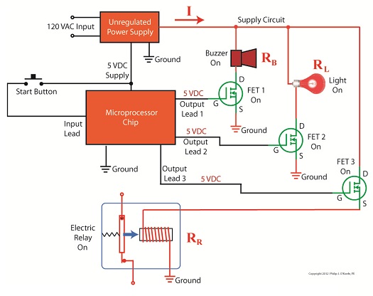
Last time we looked at a circuit schematic containing an unregulated power supply. This power supply was connected to an external supply circuit containing a number of components such as electric relays, buzzers, and lights. Each of these components has a resistance factor, and combined they have a total resistance of RTotal. We saw that when RTotal increases, the electrical current, I, decreases, and when RTotal decreases, I increases. In contrast to this increasing/decreasing activity of the total resistance RTotal, the fixed internal resistance of the unregulated power supply, RInternal, doesn’t fluctuate. Let’s explore Ohm’s Law further to see how the static effect of RInternal combines with the changing resistance present in RTotal to adversely affect the unregulated power supply output voltage, VOutput, causing it to fluctuate.
Figure 1
In Figure 1 RTotal and RInternal are operating in series, meaning they are connected together like sausage links. In this configuration their two resistances add together as if they were one larger resistor. Generally speaking, Ohm’s Law sets out that the current, I, flowing through a resistor in an electrical circuit equals the voltage, V, applied to the resistor divided by the resistance R, or: I = V ÷ R In the case of the circuit represented in Figure 1, the resistors RInternal and RTotal are connected in series within the circuit, so their resistances must be added together to arrive at a total power demand. Voltage is applied to these two resistors by the same voltage source, VDC. So, for the circuit as a whole Ohm’s Law would be written as: I = VDC ÷ (RInternal + RTotal) But, Ohm’s Law can also be applied to individual parts within the circuit, just as it can be applied to a single kitchen appliance being operated on a circuit shared with other appliances. Let’s see how this applies to our example circuit’s RTotal next week. ____________________________________________ |


