Posts Tagged ‘limiting resistor’
Transistors – Voltage Regulation Part XVI
Monday, November 5th, 2012
Transistors – Voltage Regulation Part XIII
Monday, October 15th, 2012|
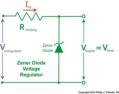
Last time we learned how the Zener diode, an excellent negotiator of current, is involved in a constant trade off, exchanging current for voltage so as to maintain a constant voltage. It draws as much current through it as is required to maintain a consistent voltage value across its leads, essentially acting as voltage regulator in order to protect sensitive electronic components from power fluctuations. Now let’s revisit our example power supply circuit and see how Ohm’s Law is used to determine the amount of electric current, IPS, that flows from the unregulated power supply and why this is important to the function of the Zener diode. See Figure 1.
Figure 1
If you’ll recall, Ohm’s Law states that current flowing through a resistor is equal to the voltage across the resistor divided by its electrical resistance. In our example that would be IPS flowing through to RLimiting. In fact, the voltage across RLimiting is the difference between the voltages at each of its ends. Applying this knowledge to our circuit, the voltage on one end is VUnregulated, while the voltage at the other is VZener. According to Ohm’s Law the equation which allows us to solve for IPS is written as: IPS = (VUnregulated – VZener) ÷ RLimiting And if we have a situation where VUnregulated equals VZener , such as when the voltage of an unregulated power supply like a battery equals the Zener voltage of a Zener diode, then the equation becomes: (VUnregulated – VZener ) = 0 And if this is true, then the following is also true: IPS = 0 ÷ RLimiting = 0 In other words, this equation tells us that if VUnregulated is equal to VZener, then the current IPS will cease to flow from the unregulated portion of the circuit towards the Zener diode and the external supply circuit. Put another way, in order for IPS to flow and the circuit to work, VUnregulated must be greater than VZener. Next week we’ll continue our discussion and see why the resistor RLimiting is necessary in order to prevent the circuit from self destructing. ____________________________________________ |

Transistors – Voltage Regulation Part XII
Sunday, October 7th, 2012|
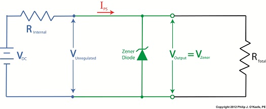
Let’s continue our discussion with regard to the example circuit discussed last time and see how the Zener diode works in tandem with the limiting resistor to control current flow and hold the output voltage at a constant level.
Figure 1
To recap our discussion from last week, the unregulated power supply portion of the circuit in Figure 1 generates an unregulated voltage, VUnregulated. Then the Zener diode, which acts as a voltage regulator, takes in VUnregulated and converts it into a steady output voltage, VOutput. Because these output terminals are connected to the ends of the Zener diode, VOutput is equal to the voltage put out by it, denoted as VZener. The Zener diode, an excellent negotiator of current, is essentially involved in a constant trade off, substituting electric current that originates in the unregulated power supply portion of the circuit for voltage, VOutput, that will serve to power the external supply circuit. In other words, the Zener diode draws as much current, IZ, through it as it needs, its objective being to keep VOutput at a constant level, and it will continue to provide this constant output, despite the fact that VUnregulated varies considerably. So, where does the current IZ come from? From IPS, that is, the current flowing from the unregulated power supply area, as shown in Figure 1. IPS flows through the limiting resistor to a junction within the circuit. At this junction, IZ splits off from IPS and continues on to the Zener diode, while current I splits off from IPS on its way to the total internal resistance, RTotal, in the external supply circuit. What this means is that when you add IZ and I together, you get IPS. Mathematically speaking this is represented as: IPS = IZ + I Why solve for IPS? We’ll see why this is important when we revisit Ohm’s Law next week and gain a fuller understanding of how IPS, VUnregulated, VZener, and RLimiting relate to each other with regard to the Zener diode. ____________________________________________ |
Transistors – Voltage Regulation Part XI
Monday, October 1st, 2012|
Without limits on our roadways things would get quickly out of hand. Imagine speeding down an unfamiliar highway and suddenly coming upon a sharp curve. With no speed limit sign to warn you to reduce speed, you could lose control of your car. Limits are useful in many situations, including within electronic circuits to keep them from getting damaged, as we’ll see in a moment.
Last time we introduced the Zener diode and the fact that it performs as a voltage regulator, enabling devices connected to it to have smooth, uninterrupted operation at a constant voltage. Let’s see how it works.
Figure 1
In Figure 1 we have an unregulated power supply circuit introduced in a previous article in this series. We learned that this power supply’s major shortcoming is that its output voltage, VOutput, is unregulated, in other words, it’s not constant. It varies with changes in the direct current supply voltage, VDC. It also varies with changes in, RTotal, which is the total internal resistance of components connected to it. RTotal changes when components are turned on and off by microprocessor and digital logic chips. When VOutput is not constant, those chips can malfunction, causing the device to operate erratically or not at all. But we can easily address this problem by adding a Zener diode voltage regulator between the unregulated power supply and the external supply circuit. See the green portion of Figure 2.
Figure 2
Our power supply now consists of a Zener diode and a limiting resistor, RLimiting. The limiting resistor does as its name implies, it limits the amount of electric current, IZ, flowing through the Zener diode. Without this limiting resistor, IZ could get high enough to damage the diode, resulting in system failure. Next time we’ll see how the Zener diode works in tandem with the limiting resistor to control current flow and hold the output voltage at a constant level. ____________________________________________ |


