|
Last time we learned how the Zener diode, an excellent negotiator of current, is involved in a constant trade off, exchanging current for voltage so as to maintain a constant voltage. It draws as much current through it as is required to maintain a consistent voltage value across its leads, essentially acting as voltage regulator in order to protect sensitive electronic components from power fluctuations. Now let’s revisit our example power supply circuit and see how Ohm’s Law is used to determine the amount of electric current, IPS, that flows from the unregulated power supply and why this is important to the function of the Zener diode. See Figure 1.
Figure 1
If you’ll recall, Ohm’s Law states that current flowing through a resistor is equal to the voltage across the resistor divided by its electrical resistance. In our example that would be IPS flowing through to RLimiting. In fact, the voltage across RLimiting is the difference between the voltages at each of its ends. Applying this knowledge to our circuit, the voltage on one end is VUnregulated, while the voltage at the other is VZener. According to Ohm’s Law the equation which allows us to solve for IPS is written as: IPS = (VUnregulated – VZener) ÷ RLimiting And if we have a situation where VUnregulated equals VZener , such as when the voltage of an unregulated power supply like a battery equals the Zener voltage of a Zener diode, then the equation becomes: (VUnregulated – VZener ) = 0 And if this is true, then the following is also true: IPS = 0 ÷ RLimiting = 0 In other words, this equation tells us that if VUnregulated is equal to VZener, then the current IPS will cease to flow from the unregulated portion of the circuit towards the Zener diode and the external supply circuit. Put another way, in order for IPS to flow and the circuit to work, VUnregulated must be greater than VZener. Next week we’ll continue our discussion and see why the resistor RLimiting is necessary in order to prevent the circuit from self destructing. ____________________________________________ |
Posts Tagged ‘battery’
Transistors – Voltage Regulation Part XIII
Monday, October 15th, 2012
Transistors – Voltage Regulation Part VII
Monday, September 3rd, 2012| Back when television had barely escaped the confines of black and white transmission there was a men’s clothing store commercial whose slogan still sticks in my mind, “Large and small, we fit them all.” It’s a nice concept, but unfortunately the same doesn’t always apply to electronic power supplies.
Last time we learned that when the electrical resistance changes on an unregulated power supply its output voltage changes proportionately. This makes it unsuitable for powering devices like microprocessor chips, which require an unchanging voltage to operate properly. Now let’s look at another shortcoming of unregulated power supplies, that being how one supply can’t fit both large and small voltage requirements. Figure 1 shows the components of a simple unregulated power supply.
Figure 1
The diagram illustrates the voltage changes taking place as electric current passes through the supply’s four components, which ultimately results in the conversion of 120 volts alternating current (VAC) into 12 volts direct current (VDC). First the transformer converts the 120 VAC from the wall outlet to the 12 volts required by most electronic devices. These voltages are shown at Points A and B. The voltage being put out by the transformer results in waves of energy which alternate between a positive maximum value, then to zero, and finally to a maximum negative value. But we want our power supply to produce 12 VDC. By VDC, I mean voltage that never falls to zero and stays at a positive 12 volts direct current consistently. This is when the diode bridge and capacitor come into play. The diode bridge consists of four electronic components, the diodes, which are connected together to form a bridge and uses semiconductor technology to transform negative voltage from the transformer into positive. The result is a series of 12 volt peaks as shown at Point C. But we still have the problem of zero voltage gaps between each peak. You see, over time the voltage at Point C of Figure 1 keeps fluctuating between 0 volts and positive 12 volts, and this is not suitable to power most electronics, which require a steady VDC current. We can get around this problem by feeding voltage from the diode bridge into the capacitor. When we do that, we eliminate the zero voltage gaps between the peaks. This happens when the capacitor charges up with electrical energy as the voltage from the diode bridge nears the top of a peak. Then, as voltage begins its dive back to zero the capacitor discharges its electrical energy to fill in the gaps between peaks. In other words it acts as a kind of reserve battery. The result is the rippled voltage pattern observed at Point D. With the current gaps filled in, the voltage is now a steady VDC. The output voltage of the unregulated power supply is totally dependant on the design of the transformer, which in this case is designed to convert 120 volts into 12 volts. This limits the power supply’s usefulness because it can only supply one output voltage, that being 12 VDC. This voltage may be insufficient for some electronics, like those often found in microprocessor controlled devices where voltages can range between 1.5 and 24 volts. Next time we’ll illustrate this limitation by revisiting our microprocessor control circuit example and trying to fit this unregulated power supply into it. ____________________________________________ |

The Microwave Oven — More on How AC Becomes DC
Monday, August 15th, 2011| The world of electricity is full of mysteries and often unanticipated outcomes, and if you’ve been reading along with my blog series you have been able to appreciate and come to some understanding of a fair number of them. This week’s installment will be no exception.
Last week we looked briefly at the high voltage circuit within a microwave oven. We discovered that the circuit contains a transformer that raises 120 volts alternating current (AC) to a much higher voltage, around 4000 volts AC. The circuit then transforms the AC into direct current (DC) with the help of electronic components known as a diode and capacitor. Let’s take a closer look at how the diode and capacitor work together to make AC into DC. Let’s follow an AC wave with the aid of a device called an oscilloscope. An oscilloscope takes in an electronic signal, measures it, graphs it, and shows it on a display screen so you can see how the signal changes over time. An AC wave is shown in Figure 1 as it would appear on an oscilloscope. Figure 1 – Alternating Current Wave You can see that each wave cycle starts with a zero value, climbs to a positive maximum value, then back to zero, and finally back down to a maximum negative value. The current keeps alternating between positive and negative polarity, hence the name “alternating current.” Within the microwave oven’s high voltage circuitry the transformer does the job of changing, or transforming if you will, 120 volts AC into 4000 volts AC. This high voltage is needed to make electrons leave the cathode in the magnetron and move them towards the anode to generate microwaves. But we’re not done with the transformation process yet. The magnetron requires DC to operate, not AC. DC current remains constant over time, maintaining a consistent positive value as shown in Figure 2. It is this type of consistency that the magnetron needs to operate.
Figure 2 – Direct Current The microwave’s diode and capacitor work together to convert the 4000 volts AC into something which resembles 4000 volts DC. First the diode acts like a one-way valve, passing the flow of positive electric current and blocking the flow of negative current. It effectively chops off the negative part of the AC wave, leaving only positive peaks, as shown in Figure 3.
Figure 3 – The Diode Chops Off The Negative Part of the AC Wave Between the peaks are gaps where there is zero current, and this is when the capacitor comes into play. Capacitors are similar to batteries because they can be charged with electrical energy and then discharge that energy when needed. Unlike a battery, the capacitor charges and discharges very quickly, within a fraction of a second. Within the circuitry of a microwave oven the capacitor charges up at the top of each peak in Figure 3, then, when the current drops to zero inside the gaps the capacitor comes into play, discharging its electrical energy into the high voltage circuit. The result is an elimination of the zero current gaps. The capacitor acts as a reserve energy supply to fill in the gaps between the peaks and keep current continually flowing to the magnetron. We have now witnessed a mock DC current situation being created, and the result is shown in Figure 4.
Figure 4 – The Capacitor Discharges to Fill In The Gaps Between Peaks The output of this approximated DC current looks like a sawtooth pattern instead of the straight line of a true DC current shown in Figure 2. This ripple pattern is evidence of the “hoax” that has been played with the AC current. The net result is that the modified AC current, thanks to the introduction of the diode and energy storing capacitor, has made an effective enough approximation of DC current to allow our magnetron to get to work jostling electrons loose from the cathode and putting our microwave oven into action. You now have a basic understanding of how to turn AC into an effective approximation of DC current. Next week we’ll find out how this high voltage circuit can prove to be lethal, even when the microwave oven is unplugged. ____________________________________________ |


Transformers – Alternating Current Does the Trick
Sunday, December 12th, 2010| If you’ve seen the movie The Prestige, you know just how “tricky” electricity can be, and if you haven’t seen it yet, you’ve yet to see a great movie. In it, Hugh Jackman uses the magical properties of electricity to pull off a magic trick the likes of which the world has never seen. But that’s all I’ll say about that… see the movie.
In 1886, a young American inventor named William Stanley did some serious thinking about Michael Faraday, the British scientist we introduced last week, and his work with electricity and magnetism. Stanley figured out how to put it all together. The result was the world’s first electrical transformer. What fueled Stanley’s curiosity? Like most good inventors, he perceived a need and sought to fill it. At the time George Westinghouse was developing his alternating current (AC) electric utility power system, the same basic system we use today. As Westinghouse’s chief engineer, Stanley was given the task of figuring out a way to efficiently change voltage levels on an AC power grid. The industrial revolution was in full swing, and for various industrial purposes factories needed to operate on voltage levels different from those produced by the Westinghouse generators. Stanley approached the task before him with the benefit of knowledge supplied by Faraday’s experimentation. He knew that Faraday was able to cause current to flow through a wire by moving a magnet near it back and forth. This phenomenon occurred because lines of magnetic flux were varying over time with respect to the wire through the magnet’s movement. Being aware of the vicissitudes of alternating current, the way it varies in intensity and direction, Stanley was able to conclude that any lines of magnetic flux generated by AC current flowing through a coiled wire would also tend to vary over time. Armed with this knowledge, Stanley replaced the DC battery used in Faraday’s experiment with an AC generator. This modified setup is shown in Figure 1.
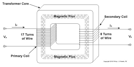
Figure 1 – Faraday’s Experiment Modified With An AC Power Source In the modified setup the switch is closed, causing the AC power flowing through the first coiled wire to create lines of magnetic flux in the iron rod. These lines of flux continually vary and thus induce AC flow in the second coil. The action taking place is duly recorded by a Galvanometer needle, which keeps moving so long as the switch remains closed. Stanley also knew that the voltage created in the second coiled wire was dependent on how many turns, or loops, of wire were present in it compared to the number of turns of wire in the first coil. He made the observation that if less turns were present in the second coiled wire as compared to the first, less voltage would also be emitted from the second coiled wire. This demonstrates the phenomenon of changing voltage with respect to supply delivered by the AC generator to the first coil. Putting these findings together, Stanley was able to develop the first practical electrical transformer, whose basic design is shown in Figure 2. Here we see that the iron rod from Faraday’s experiment has been replaced with an iron transformer core resembling a squared off doughnut.
Figure 2 – A Basic Electrical Transformer Next time we’ll get into the math behind this discussion, and we’ll see how Stanley’s transformer worked. _____________________________________________ |


