| Back when television had barely escaped the confines of black and white transmission there was a men’s clothing store commercial whose slogan still sticks in my mind, “Large and small, we fit them all.” It’s a nice concept, but unfortunately the same doesn’t always apply to electronic power supplies.
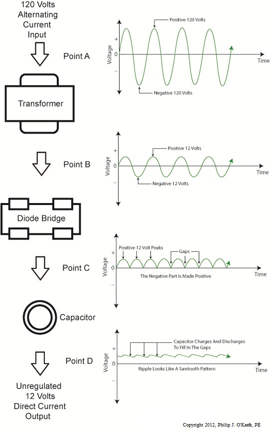
Last time we learned that when the electrical resistance changes on an unregulated power supply its output voltage changes proportionately. This makes it unsuitable for powering devices like microprocessor chips, which require an unchanging voltage to operate properly. Now let’s look at another shortcoming of unregulated power supplies, that being how one supply can’t fit both large and small voltage requirements. Figure 1 shows the components of a simple unregulated power supply. Figure 1
The diagram illustrates the voltage changes taking place as electric current passes through the supply’s four components, which ultimately results in the conversion of 120 volts alternating current (VAC) into 12 volts direct current (VDC). First the transformer converts the 120 VAC from the wall outlet to the 12 volts required by most electronic devices. These voltages are shown at Points A and B. The voltage being put out by the transformer results in waves of energy which alternate between a positive maximum value, then to zero, and finally to a maximum negative value. But we want our power supply to produce 12 VDC. By VDC, I mean voltage that never falls to zero and stays at a positive 12 volts direct current consistently. This is when the diode bridge and capacitor come into play. The diode bridge consists of four electronic components, the diodes, which are connected together to form a bridge and uses semiconductor technology to transform negative voltage from the transformer into positive. The result is a series of 12 volt peaks as shown at Point C. But we still have the problem of zero voltage gaps between each peak. You see, over time the voltage at Point C of Figure 1 keeps fluctuating between 0 volts and positive 12 volts, and this is not suitable to power most electronics, which require a steady VDC current. We can get around this problem by feeding voltage from the diode bridge into the capacitor. When we do that, we eliminate the zero voltage gaps between the peaks. This happens when the capacitor charges up with electrical energy as the voltage from the diode bridge nears the top of a peak. Then, as voltage begins its dive back to zero the capacitor discharges its electrical energy to fill in the gaps between peaks. In other words it acts as a kind of reserve battery. The result is the rippled voltage pattern observed at Point D. With the current gaps filled in, the voltage is now a steady VDC. The output voltage of the unregulated power supply is totally dependant on the design of the transformer, which in this case is designed to convert 120 volts into 12 volts. This limits the power supply’s usefulness because it can only supply one output voltage, that being 12 VDC. This voltage may be insufficient for some electronics, like those often found in microprocessor controlled devices where voltages can range between 1.5 and 24 volts. Next time we’ll illustrate this limitation by revisiting our microprocessor control circuit example and trying to fit this unregulated power supply into it. ____________________________________________ |
Tags: battery, capacitor, current, diode, diode bridge, electrical resistance, electronic power supply, electronics, engineering expert witness, forensic engineer, microprocessor control, microprocessor control circuit, transformer, unregulated power supply, VAC, VDC, voltage, voltage regulation, volts alternating current, volts direct current, wall outlet, wave


