| Back in the early 1970s my dad, a notorious tightwad, coughed up several hundred dollars to buy his first portable color television. That was a small fortune back then. The TV was massive, standing at 24 inches wide, 18 inches high, and 24 inches deep, and weighing in at about 50 pounds. I think the only thing that made this behemoth “portable” was the fact that it had a carrying handle on top.
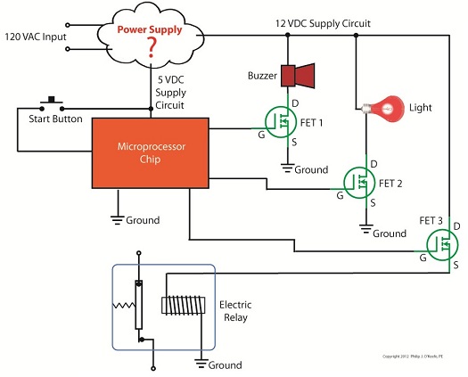
A major reason for our old TV being so big and clunky was of course due to limitations in technology of the time. Many large, heavy, and expensive electronic components were needed to make it work, requiring a lot of space for the circuitry. By comparison, modern flat screen televisions and other electronic devices are small and compact because advances in technology enable them to work with far fewer electronic components. These components are also smaller, lighter, and cheaper. Last time we looked at the components of a simple unregulated power supply to see how it converts 120 volts alternating current (VAC) to 12 volts direct current (VDC). We discovered that the output voltage of the supply is totally dependent on the design of the transformer, because the transformer in our example can only produce one voltage, 12 VDC. This of course limits the supply’s usefulness in that it is unable to power multiple electronic devices requiring two or more voltages, such as we’ll be discussing a bit further down. Now let’s illustrate this power supply limitation by revisiting our microprocessor control circuit example which we introduced in a previous article in this series on transistors. Figure 1
In Figure 1 we have to decide what kind of power to supply to the circuit, but we have a problem. Sure, the unregulated power supply that we just discussed is up to the task of providing the 12 VDC needed to supply power for the buzzer, light, and electric relay. But let’s not forget about powering the microprocessor chip. It needs only 5 VDC to operate and will get damaged and malfunction on the higher 12 VDC the current power supply provides. Our power supply just isn’t equipped to provide the two voltages required by the circuit. We could try and get around this problem by adding a second unregulated power supply with a transformer designed to convert 120 VAC to 5 VAC. But, reminiscent of the circuitry in my dad’s clunky old portable color TV, the second power supply would require substantially more space in order to accommodate an additional transformer, diode bridge, and capacitor. Another thing to consider is that transformers aren’t cheap, and they tend to have some heft to them due to their iron cores, so more cost and weight would be added to the circuit as well. For these reasons the use of a second power supply is a poor option. Next time we’ll look at how adding a transistor voltage regulator circuit to the supply results in cost, size, and weight savings. It also results in a more flexible and dependable output voltage. ____________________________________________ |
Posts Tagged ‘volts alternating current’
Transistors – Voltage Regulation Part VIII
Sunday, September 9th, 2012Transistors – Voltage Regulation Part VII
Monday, September 3rd, 2012| Back when television had barely escaped the confines of black and white transmission there was a men’s clothing store commercial whose slogan still sticks in my mind, “Large and small, we fit them all.” It’s a nice concept, but unfortunately the same doesn’t always apply to electronic power supplies.
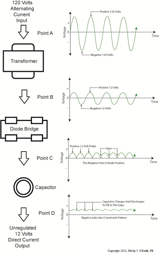
Last time we learned that when the electrical resistance changes on an unregulated power supply its output voltage changes proportionately. This makes it unsuitable for powering devices like microprocessor chips, which require an unchanging voltage to operate properly. Now let’s look at another shortcoming of unregulated power supplies, that being how one supply can’t fit both large and small voltage requirements. Figure 1 shows the components of a simple unregulated power supply. Figure 1
The diagram illustrates the voltage changes taking place as electric current passes through the supply’s four components, which ultimately results in the conversion of 120 volts alternating current (VAC) into 12 volts direct current (VDC). First the transformer converts the 120 VAC from the wall outlet to the 12 volts required by most electronic devices. These voltages are shown at Points A and B. The voltage being put out by the transformer results in waves of energy which alternate between a positive maximum value, then to zero, and finally to a maximum negative value. But we want our power supply to produce 12 VDC. By VDC, I mean voltage that never falls to zero and stays at a positive 12 volts direct current consistently. This is when the diode bridge and capacitor come into play. The diode bridge consists of four electronic components, the diodes, which are connected together to form a bridge and uses semiconductor technology to transform negative voltage from the transformer into positive. The result is a series of 12 volt peaks as shown at Point C. But we still have the problem of zero voltage gaps between each peak. You see, over time the voltage at Point C of Figure 1 keeps fluctuating between 0 volts and positive 12 volts, and this is not suitable to power most electronics, which require a steady VDC current. We can get around this problem by feeding voltage from the diode bridge into the capacitor. When we do that, we eliminate the zero voltage gaps between the peaks. This happens when the capacitor charges up with electrical energy as the voltage from the diode bridge nears the top of a peak. Then, as voltage begins its dive back to zero the capacitor discharges its electrical energy to fill in the gaps between peaks. In other words it acts as a kind of reserve battery. The result is the rippled voltage pattern observed at Point D. With the current gaps filled in, the voltage is now a steady VDC. The output voltage of the unregulated power supply is totally dependant on the design of the transformer, which in this case is designed to convert 120 volts into 12 volts. This limits the power supply’s usefulness because it can only supply one output voltage, that being 12 VDC. This voltage may be insufficient for some electronics, like those often found in microprocessor controlled devices where voltages can range between 1.5 and 24 volts. Next time we’ll illustrate this limitation by revisiting our microprocessor control circuit example and trying to fit this unregulated power supply into it. ____________________________________________ |


