Posts Tagged ‘transistor’
Transistors – Voltage Regulation Part XV
Sunday, October 28th, 2012

Transistors – Voltage Regulation Part XI
Monday, October 1st, 2012|
Without limits on our roadways things would get quickly out of hand. Imagine speeding down an unfamiliar highway and suddenly coming upon a sharp curve. With no speed limit sign to warn you to reduce speed, you could lose control of your car. Limits are useful in many situations, including within electronic circuits to keep them from getting damaged, as we’ll see in a moment.
Last time we introduced the Zener diode and the fact that it performs as a voltage regulator, enabling devices connected to it to have smooth, uninterrupted operation at a constant voltage. Let’s see how it works.
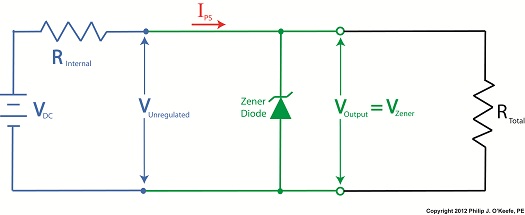
Figure 1
In Figure 1 we have an unregulated power supply circuit introduced in a previous article in this series. We learned that this power supply’s major shortcoming is that its output voltage, VOutput, is unregulated, in other words, it’s not constant. It varies with changes in the direct current supply voltage, VDC. It also varies with changes in, RTotal, which is the total internal resistance of components connected to it. RTotal changes when components are turned on and off by microprocessor and digital logic chips. When VOutput is not constant, those chips can malfunction, causing the device to operate erratically or not at all. But we can easily address this problem by adding a Zener diode voltage regulator between the unregulated power supply and the external supply circuit. See the green portion of Figure 2.
Figure 2
Our power supply now consists of a Zener diode and a limiting resistor, RLimiting. The limiting resistor does as its name implies, it limits the amount of electric current, IZ, flowing through the Zener diode. Without this limiting resistor, IZ could get high enough to damage the diode, resulting in system failure. Next time we’ll see how the Zener diode works in tandem with the limiting resistor to control current flow and hold the output voltage at a constant level. ____________________________________________ |


Transistors – Voltage Regulation Part VIII
Sunday, September 9th, 2012| Back in the early 1970s my dad, a notorious tightwad, coughed up several hundred dollars to buy his first portable color television. That was a small fortune back then. The TV was massive, standing at 24 inches wide, 18 inches high, and 24 inches deep, and weighing in at about 50 pounds. I think the only thing that made this behemoth “portable” was the fact that it had a carrying handle on top.
A major reason for our old TV being so big and clunky was of course due to limitations in technology of the time. Many large, heavy, and expensive electronic components were needed to make it work, requiring a lot of space for the circuitry. By comparison, modern flat screen televisions and other electronic devices are small and compact because advances in technology enable them to work with far fewer electronic components. These components are also smaller, lighter, and cheaper. Last time we looked at the components of a simple unregulated power supply to see how it converts 120 volts alternating current (VAC) to 12 volts direct current (VDC). We discovered that the output voltage of the supply is totally dependent on the design of the transformer, because the transformer in our example can only produce one voltage, 12 VDC. This of course limits the supply’s usefulness in that it is unable to power multiple electronic devices requiring two or more voltages, such as we’ll be discussing a bit further down. Now let’s illustrate this power supply limitation by revisiting our microprocessor control circuit example which we introduced in a previous article in this series on transistors.
Figure 1
In Figure 1 we have to decide what kind of power to supply to the circuit, but we have a problem. Sure, the unregulated power supply that we just discussed is up to the task of providing the 12 VDC needed to supply power for the buzzer, light, and electric relay. But let’s not forget about powering the microprocessor chip. It needs only 5 VDC to operate and will get damaged and malfunction on the higher 12 VDC the current power supply provides. Our power supply just isn’t equipped to provide the two voltages required by the circuit. We could try and get around this problem by adding a second unregulated power supply with a transformer designed to convert 120 VAC to 5 VAC. But, reminiscent of the circuitry in my dad’s clunky old portable color TV, the second power supply would require substantially more space in order to accommodate an additional transformer, diode bridge, and capacitor. Another thing to consider is that transformers aren’t cheap, and they tend to have some heft to them due to their iron cores, so more cost and weight would be added to the circuit as well. For these reasons the use of a second power supply is a poor option. Next time we’ll look at how adding a transistor voltage regulator circuit to the supply results in cost, size, and weight savings. It also results in a more flexible and dependable output voltage. ____________________________________________ |

Transistors – Digital Control Interface, Part V
Sunday, July 15th, 2012| Last time we looked at my electric relay solution to a problem presented by a 120 volt alternating current (VAC) drive motor operating within an x-ray film processing machine. Now let’s see what happens when we press the button to set the microprocessor into operation.
Figure 1Figure 1 shows that when the button is depressed, the computer program contained within the microprocessor chip goes into action, signaling the start of the control initiative. 5 volts direct current (VDC) is supplied to Output Lead 2, and FET 2 (Field Effect Transistor 2) becomes activated, which allows electric current from the 12 VDC supply to course into the 12 VDC electric relay, through the relay’s wire coil, then conclude its travel into electrical ground. The electric relay components, including a wire coil, steel armature, spring, and normally open (N.O.) contact, are shown within a blue box in our illustration. Current flow is represented by red lines. The control initiative passes from the microprocessor to FET 2, and then to the 12 VDC electric relay, just as the Olympic Torch is relayed through a system of runners. We learned in one of my previous articles on industrial control that when an electric relay coil is energized, electromagnetic attraction pulls its steel armature towards the wire coil and the N.O. electrical contact. In Figure 1 this attraction is represented by a blue arrow. With the N.O. contact closed the drive motor is connected to the 120 VAC input, and the motor is activated.
Figure 2
Figure 2 shows what happens after the button is depressed. The computer program is activated, directing the microprocessor chip to keep 5 VDC on Output Lead 2 and FET 2 while the prerequisite 40 minutes elapses. Thus the relay remains energized and the motor remains on during this time.
Figure 3
In Figure 3, at the end of the 40 minute countdown, the computer program applies 0 VDC to Output Lead 2. FET 2 then turns off the current flow to the relay and it begins to de-energize, causing the spring to pull the steel armature away from the N.O. contact and the 120 VAC power supply to be interrupted. The motor is deactivated. At the same time, the computer program applies 5 VDC to Output Lead 1 and FET 1 for 2 seconds. FET 1 turns on the flow of current through the buzzer, causing it to sound off and signal that the x-ray film processing machine is ready for use. Next time we’ll look at how transistors are used to regulate voltage within direct current power supplies like the one shown in Figure 3 above. ____________________________________________ |


Transistors – Digital Control Interface, Part IV
Monday, July 9th, 2012| The Olympic Torch relay, soon to culminate in London, is the grand daddy of all relays, starting in one country, traversing many others, then ending its journey at the site of the Olympic Games. It passes through many athletes’ hands while on its journey, its final purpose being to light the Olympic Flame. Less glamorous, though still useful, is the relay race that often takes place within digital controls.
Last time we looked at my design solution for the control of a microprocessor controlled medical x-ray film developing machine, where a field effect transistor (FET) acted as a digital control interface between a 5 volt direct current (VDC) microprocessor and a 12 VDC buzzer. Well, controlling the buzzer wasn’t the only function of the microprocessor. It also had to control a 120 volt alternating current (VAC) drive motor, the purpose of which was to move x-ray film through a series of processes within the machine. Yet another requirement was that the machine’s drive motor run 40 minutes upon activation by a start button, then shut off. One of the challenges presented by this specification was that an FET standing alone is only suited to control direct current devices like the buzzer, but not alternating current devices like electric motors. Direct current flows in one direction only when traveling through wire, and since an FET can only pass current in one direction it is the perfect match for those applications. Now, as the name would imply, alternating current flow alternates, that is, it reverses direction and varies in intensity many times each second. This is a scenario that FETs are not equipped to handle because they can’t deal with reverse flow. This meant that, for the purpose of my developing machine, I could not use an FET to directly control the 120 VAC motor. Now let’s take a look at Figure 1 to get a basic look at how I solved the problem. |

Transistors – Digital Control Interface, Part I
Monday, June 18th, 2012| In the navy, the captain is the brains behind a ship’s operations. He gathers information, makes important decisions, then issues orders. He’s not there to roll up his sleeves and swab the decks. The captain relies on the ship’s officers to act as an interface between himself and the sailors that perform the physical labor required on deck.
In this article we’ll see how the FET, that is, the field effect transistor, performs much the same role as the ship’s officers when it is used within electronic controls. There it acts as an interface between electronic components that issue commands and the electrical devices that carry them out. Last week we became familiar with field effect transistors and how their control of electrical current flow is analogous to how a faucet controls the flow of water. Although FETs can be used to vary the flow of current, they’re usually employed to perform a much simpler task, that of simply turning flow on or off, with no in-between modality. Like the captain of a ship, microprocessor and logic chips are the brains behind the operation in all sorts of industrial and consumer electronics. Figure 1 shows a few of them. Figure 1
The chips, which operate on low voltage, contain entire computer programs within them that gather information, make decisions, then instruct the higher voltage devices like motors, electrical relays, light bulbs, and audible alarms to follow. By “information,” I mean data signals received by the chip from its input connections to sensors, buttons, and other electrical components. This data informs the chip’s computer program of important operational information, like whether buttons have been pressed, switches are activated, and temperatures are normal. Based on this data, “decisions” are made by the chip using the logic contained within its program, then, depending on the decisions made, “commands” are issued by the chip. The commands, in the form of electrical output signals, are put into action by the work horses, the higher voltage devices. They, like a ship’s sailors, perform the actual physical work. There is one problem presented by this scenario, however. The electric output signals from the lower voltage chips are not suited to directly control the higher voltage devices because the signal voltage put out by the chips is too low. Even if the chip was designed to work at a higher voltage, the high level of current drawn by the motors, relays, and bulbs would lead to damage of the delicate circuitry within the chip. The chips must therefore rely on the FET to act as a digital control interface between them and the higher voltage devices, much as the ship’s captain depends on his subordinates to carry out his orders. Next week we’ll look at a real life example of how a digital interface is put into operation within an industrial product.
____________________________________________ |


