| Electrical voltage flow and water flow have a lot in common. They’re both affected by fluctuations in supply, fluctuations which can adversely impact both performance and equipment integrity. Take for example a sprinkler that fails to cover a designated section of lawn due to heavy neighborhood demand. Everybody wants to water on the weekend when it’s been 90 degrees all week, and low water pressure is the result. There are times when it’s hard to get a glass of water. By contrast in the winter months, when water demands tend to be lower, water supplies are plentiful. This scenario of varying water pressure is analogous to what sometimes occurs within electric circuits.
In my previous blog article on wall warts, I described the operation of a simple power supply consisting of a transformer, diode bridge, and capacitor. Together, these components converted 120 volts alternating current (VAC) to 12 volts direct current (VDC). The wall wart power supply is fine for many applications, however it is unregulated, meaning if there are any sudden surges in power, such as spikes or dips caused by lightning strikes or other disturbances on the electric utility system, there could be problems.
Take for example a power supply that is used in conjunction with sensitive digital logic chips, like the one used in my x-ray film processor design shown in my last blog article. These chips are designed to run optimally on a constant voltage, like 5 VDC, and when that doesn’t happen input signals can fail to register with the computer program and cause a variety of problems, such as output signals turning on and off at will. In the film processor the drive motor may start at the wrong time or get stuck in an on modality. If power surges are high enough, microprocessor chips can get damaged, compromising the entire working unit. The output voltage of an unregulated power supply can also vary in response to power demand, just as when sprinklers don’t have sufficient water flow to cover a section of lawn. Demand for power can change within a circuit when electrical components like relays, lights, and buzzers are turned on and off by digital logic chips. Next time we’ll take a look at a basic concept of electrical engineering known as “Ohm’s Law” and how it governs the variable output voltage response of unregulated power supplies.
____________________________________________ |
Posts Tagged ‘drive motor’
Transistors – Voltage Regulation
Sunday, July 22nd, 2012Transistors – Digital Control Interface, Part IV
Monday, July 9th, 2012| The Olympic Torch relay, soon to culminate in London, is the grand daddy of all relays, starting in one country, traversing many others, then ending its journey at the site of the Olympic Games. It passes through many athletes’ hands while on its journey, its final purpose being to light the Olympic Flame. Less glamorous, though still useful, is the relay race that often takes place within digital controls.
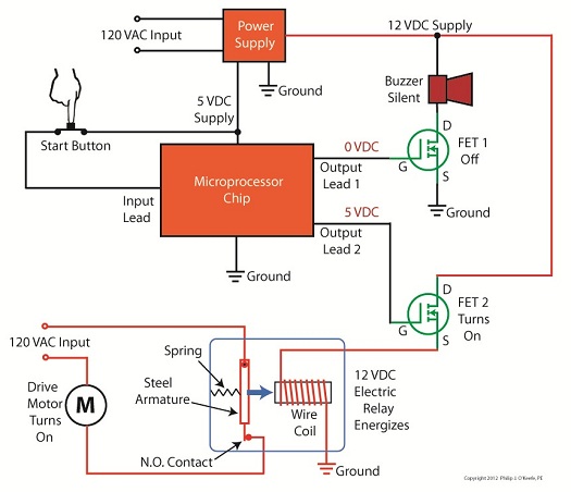
Last time we looked at my design solution for the control of a microprocessor controlled medical x-ray film developing machine, where a field effect transistor (FET) acted as a digital control interface between a 5 volt direct current (VDC) microprocessor and a 12 VDC buzzer. Well, controlling the buzzer wasn’t the only function of the microprocessor. It also had to control a 120 volt alternating current (VAC) drive motor, the purpose of which was to move x-ray film through a series of processes within the machine. Yet another requirement was that the machine’s drive motor run 40 minutes upon activation by a start button, then shut off. One of the challenges presented by this specification was that an FET standing alone is only suited to control direct current devices like the buzzer, but not alternating current devices like electric motors. Direct current flows in one direction only when traveling through wire, and since an FET can only pass current in one direction it is the perfect match for those applications. Now, as the name would imply, alternating current flow alternates, that is, it reverses direction and varies in intensity many times each second. This is a scenario that FETs are not equipped to handle because they can’t deal with reverse flow. This meant that, for the purpose of my developing machine, I could not use an FET to directly control the 120 VAC motor. Now let’s take a look at Figure 1 to get a basic look at how I solved the problem. |


