|
Did you know that water droplets traveling at high velocity can take on the force of bullets? It can happen, particularly within steam turbines at a power plant during the process of condensation, where steam transforms back into water. The last couple of weeks in this blog series we’ve been talking about the steam and water cycle within electric utility power plants, how heat energy is added to water during the boiling process, and how turbines run on the sensible heat energy that lies within the superheated steam vapor supplied by boilers and superheaters. We learned that without a superheater there is a very real possibility that the steam’s temperature can fall to mere boiling point. When steam returns to boiling point temperature an undesirable situation is created. The steam begins to condense into water within the turbine. To understand how this happens, let’s return to our graph from last week. It illustrates the situation when there’s no superheater present in the power plant’s steam cycle.
Figure 1
After consuming all the sensible heat energy in phase C in Figure 1, the only heat energy which remains available to the turbine is the latent heat energy in phase B. If you recall from past blog articles, latent heat energy is the energy added to the boiler water to initiate the building of steam. As the turbine consumes this final source of heat energy, the steam begins a process of condensation while it flows through the turbine. You can think of condensing as a process that is opposite to boiling. During condensation, steam changes back into water as latent heat energy is consumed by the turbine. When the condensing process is in progress, the temperature in phase B remains at boiling point, but instead of pure steam flowing through the turbine, the steam will now include water droplets, a dangerous mixture. As steam flows through the progressive chambers of turbine blades, more of its latent heat energy is consumed and increasingly more steam turns back into water as the number of water droplets increases.
Figure 2 – Water Droplets Forming in the Turbine
The danger comes in when you consider that the steam/water droplet mixture is flying through the turbine at hundreds of miles per hour. At these high speeds water droplets take on the force of machine gun bullets. That’s because they act more like a solid than a liquid due to their incompressible state. In other words, under great pressure and at high speed water droplets don’t just harmlessly splash around. They hit hard and cause damage to rapidly spinning turbine blades. Without a working turbine, the generator will grind to a halt. So how do we supply the energy hungry turbine with the energy contained within high temperature superheated steam in sufficient quantities to keep things going? We’ll talk more about the superheater, its function and construction, next week.
________________________________________ |
Posts Tagged ‘damage’
Condensation Inside the Steam Turbine
Sunday, September 8th, 2013

Transistors – Voltage Regulation Part XI
Monday, October 1st, 2012|
Without limits on our roadways things would get quickly out of hand. Imagine speeding down an unfamiliar highway and suddenly coming upon a sharp curve. With no speed limit sign to warn you to reduce speed, you could lose control of your car. Limits are useful in many situations, including within electronic circuits to keep them from getting damaged, as we’ll see in a moment.
Last time we introduced the Zener diode and the fact that it performs as a voltage regulator, enabling devices connected to it to have smooth, uninterrupted operation at a constant voltage. Let’s see how it works.
Figure 1
In Figure 1 we have an unregulated power supply circuit introduced in a previous article in this series. We learned that this power supply’s major shortcoming is that its output voltage, VOutput, is unregulated, in other words, it’s not constant. It varies with changes in the direct current supply voltage, VDC. It also varies with changes in, RTotal, which is the total internal resistance of components connected to it. RTotal changes when components are turned on and off by microprocessor and digital logic chips. When VOutput is not constant, those chips can malfunction, causing the device to operate erratically or not at all. But we can easily address this problem by adding a Zener diode voltage regulator between the unregulated power supply and the external supply circuit. See the green portion of Figure 2.
Figure 2
Our power supply now consists of a Zener diode and a limiting resistor, RLimiting. The limiting resistor does as its name implies, it limits the amount of electric current, IZ, flowing through the Zener diode. Without this limiting resistor, IZ could get high enough to damage the diode, resulting in system failure. Next time we’ll see how the Zener diode works in tandem with the limiting resistor to control current flow and hold the output voltage at a constant level. ____________________________________________ |


Transistors – Voltage Regulation Part VIII
Sunday, September 9th, 2012| Back in the early 1970s my dad, a notorious tightwad, coughed up several hundred dollars to buy his first portable color television. That was a small fortune back then. The TV was massive, standing at 24 inches wide, 18 inches high, and 24 inches deep, and weighing in at about 50 pounds. I think the only thing that made this behemoth “portable” was the fact that it had a carrying handle on top.
A major reason for our old TV being so big and clunky was of course due to limitations in technology of the time. Many large, heavy, and expensive electronic components were needed to make it work, requiring a lot of space for the circuitry. By comparison, modern flat screen televisions and other electronic devices are small and compact because advances in technology enable them to work with far fewer electronic components. These components are also smaller, lighter, and cheaper. Last time we looked at the components of a simple unregulated power supply to see how it converts 120 volts alternating current (VAC) to 12 volts direct current (VDC). We discovered that the output voltage of the supply is totally dependent on the design of the transformer, because the transformer in our example can only produce one voltage, 12 VDC. This of course limits the supply’s usefulness in that it is unable to power multiple electronic devices requiring two or more voltages, such as we’ll be discussing a bit further down. Now let’s illustrate this power supply limitation by revisiting our microprocessor control circuit example which we introduced in a previous article in this series on transistors.
Figure 1
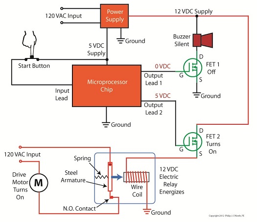
In Figure 1 we have to decide what kind of power to supply to the circuit, but we have a problem. Sure, the unregulated power supply that we just discussed is up to the task of providing the 12 VDC needed to supply power for the buzzer, light, and electric relay. But let’s not forget about powering the microprocessor chip. It needs only 5 VDC to operate and will get damaged and malfunction on the higher 12 VDC the current power supply provides. Our power supply just isn’t equipped to provide the two voltages required by the circuit. We could try and get around this problem by adding a second unregulated power supply with a transformer designed to convert 120 VAC to 5 VAC. But, reminiscent of the circuitry in my dad’s clunky old portable color TV, the second power supply would require substantially more space in order to accommodate an additional transformer, diode bridge, and capacitor. Another thing to consider is that transformers aren’t cheap, and they tend to have some heft to them due to their iron cores, so more cost and weight would be added to the circuit as well. For these reasons the use of a second power supply is a poor option. Next time we’ll look at how adding a transistor voltage regulator circuit to the supply results in cost, size, and weight savings. It also results in a more flexible and dependable output voltage. ____________________________________________ |

Transistors – Voltage Regulation
Sunday, July 22nd, 2012| Electrical voltage flow and water flow have a lot in common. They’re both affected by fluctuations in supply, fluctuations which can adversely impact both performance and equipment integrity. Take for example a sprinkler that fails to cover a designated section of lawn due to heavy neighborhood demand. Everybody wants to water on the weekend when it’s been 90 degrees all week, and low water pressure is the result. There are times when it’s hard to get a glass of water. By contrast in the winter months, when water demands tend to be lower, water supplies are plentiful. This scenario of varying water pressure is analogous to what sometimes occurs within electric circuits.
In my previous blog article on wall warts, I described the operation of a simple power supply consisting of a transformer, diode bridge, and capacitor. Together, these components converted 120 volts alternating current (VAC) to 12 volts direct current (VDC). The wall wart power supply is fine for many applications, however it is unregulated, meaning if there are any sudden surges in power, such as spikes or dips caused by lightning strikes or other disturbances on the electric utility system, there could be problems.
Take for example a power supply that is used in conjunction with sensitive digital logic chips, like the one used in my x-ray film processor design shown in my last blog article. These chips are designed to run optimally on a constant voltage, like 5 VDC, and when that doesn’t happen input signals can fail to register with the computer program and cause a variety of problems, such as output signals turning on and off at will. In the film processor the drive motor may start at the wrong time or get stuck in an on modality. If power surges are high enough, microprocessor chips can get damaged, compromising the entire working unit. The output voltage of an unregulated power supply can also vary in response to power demand, just as when sprinklers don’t have sufficient water flow to cover a section of lawn. Demand for power can change within a circuit when electrical components like relays, lights, and buzzers are turned on and off by digital logic chips. Next time we’ll take a look at a basic concept of electrical engineering known as “Ohm’s Law” and how it governs the variable output voltage response of unregulated power supplies.
____________________________________________ |


