|
Did you know that water droplets traveling at high velocity can take on the force of bullets? It can happen, particularly within steam turbines at a power plant during the process of condensation, where steam transforms back into water. The last couple of weeks in this blog series we’ve been talking about the steam and water cycle within electric utility power plants, how heat energy is added to water during the boiling process, and how turbines run on the sensible heat energy that lies within the superheated steam vapor supplied by boilers and superheaters. We learned that without a superheater there is a very real possibility that the steam’s temperature can fall to mere boiling point. When steam returns to boiling point temperature an undesirable situation is created. The steam begins to condense into water within the turbine. To understand how this happens, let’s return to our graph from last week. It illustrates the situation when there’s no superheater present in the power plant’s steam cycle.
Figure 1
After consuming all the sensible heat energy in phase C in Figure 1, the only heat energy which remains available to the turbine is the latent heat energy in phase B. If you recall from past blog articles, latent heat energy is the energy added to the boiler water to initiate the building of steam. As the turbine consumes this final source of heat energy, the steam begins a process of condensation while it flows through the turbine. You can think of condensing as a process that is opposite to boiling. During condensation, steam changes back into water as latent heat energy is consumed by the turbine. When the condensing process is in progress, the temperature in phase B remains at boiling point, but instead of pure steam flowing through the turbine, the steam will now include water droplets, a dangerous mixture. As steam flows through the progressive chambers of turbine blades, more of its latent heat energy is consumed and increasingly more steam turns back into water as the number of water droplets increases.
Figure 2 – Water Droplets Forming in the Turbine
The danger comes in when you consider that the steam/water droplet mixture is flying through the turbine at hundreds of miles per hour. At these high speeds water droplets take on the force of machine gun bullets. That’s because they act more like a solid than a liquid due to their incompressible state. In other words, under great pressure and at high speed water droplets don’t just harmlessly splash around. They hit hard and cause damage to rapidly spinning turbine blades. Without a working turbine, the generator will grind to a halt. So how do we supply the energy hungry turbine with the energy contained within high temperature superheated steam in sufficient quantities to keep things going? We’ll talk more about the superheater, its function and construction, next week.
________________________________________ |
Posts Tagged ‘generator’
Condensation Inside the Steam Turbine
Sunday, September 8th, 2013

Desuperheating in the Steam Turbine
Monday, September 2nd, 2013|
Last time we learned that the addition of a superheater to the electric utility power plant steam cycle provides a ready supply of high temperature steam, laden with heat energy, to the turbine, which in turn powers the generator. But this isn’t its only job. One of the superheater’s most important functions is to regulate the ongoing process of desuperheating that takes place as the turbine consumes heat energy. To understand this, let’s see what takes place if the superheater were to be removed from its position between the boiler and turbine.
Figure 1
Without the superheater, the only available remaining source of sensible heat energy to the turbine would come from the meager amount present in phase C steam as shown in Figure 1. If you’ll recall from a past blog, the sensible heat energy contained in superheated steam is the best source of energy for a steam turbine, because it’s able to keep it operating most efficiently. As the turbine consumes the heat energy in phase C, starting at point 3 and continuing to point 2, the steam it’s consuming is in the process of desuperheating, as evidenced by the downward slope between the two points. Desuperheating is an engineering term which means that as sensible heat energy is removed from the steam due to its use by the turbine, there will be a resulting drop in steam temperature. And if this process were to continue without the compensatory function provided by the addition of a superheater to the steam cycle, the steam’s temperature would eventually return to mere boiling point, at point 2. This is an undesirable thing. With the steam’s temperature at boiling point, the only remaining source of heat energy to the turbine is the latent heat energy of phase B. This heat energy will lead to an undesirable circumstance for the operation of our power hungry turbine as we will see next week. ________________________________________ |

Superheating, Part I
Monday, August 19th, 2013|
Last time we learned that our power plant boiler as presently designed doesn’t do a good job of producing ample amounts of superheated steam, the kind of steam that turbines need to spin and power generators. During the process of superheating the more heat energy that’s added to the steam in our boiler, the higher its temperature becomes. However, our boiler can only produce a limited amount of superheated steam as it stands now.
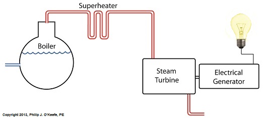
So how do we get more heat energy into the superheated steam? Take a look at the illustration below for the solution to the problem. You’ll note a prominent new addition to our illustration. It’s called a superheater. The superheater performs the function of raising the temperature of the steam produced in our boiler to the incredibly high temperatures required to run steam turbines and electrical generators down the line, as explained in my blog on steam turbines. The superheater adds more heat energy to the steam than the boiler can alone. In fact, the amount of heat energy in the superheated steam produced with our new design is proportional to the amount of electrical energy that power plant generators produce. Its addition to our setup will result in more energy supplied to the turbine, which in turn spins the generator. The result is more electricity for consumers to use and a more efficiently operating power plant. But inefficiency isn’t the only problem addressed by the superheater. We’ll see what else it can do next week. ________________________________________ |


Transformers – Something To Do With The Flux
Sunday, December 19th, 2010| Aside from the magical manifestation of innumerable top hats and replicate bodies that the movie The Prestige boasts is possible, there are many other fascinating applications of electricity, as we’ll see today.
Last time we learned how George Westinghouse’s chief engineer, William Stanley, developed the first practical transformer for electric utility use. Now let’s see how it works, as illustrated in Figure 1.
Figure 1 – The Basic Electrical Transformer What we have here is an alternating current (AC) power source. And much like an electrical generator in a utility power plant, it is connected via power lines to the primary coil wires of a transformer, such as the one which feeds power to your house. The voltage applied by the source, that is, the power plant, to the primary coil is known as VP, and the electrical current flowing through the primary coil is referred to as IP. As we learned last week, the continually varying electrical current flowing through the coil creates lines of magnetic flux, which also continually vary. In our diagram the lines of flux flow around the core of the transformer. The magnetic flux present in the core then induces AC voltage, or VS, and current, or IS, to the secondary coil when its wires are connected to something requiring an electrical load to operate. Some examples would be light bulbs, TV’s, and most appliances found in the average home. As was mentioned last week, the number of wire turns, or loops, in the secondary coil as compared to the primary coil determine how the transformer will change the voltage that is applied to it. An example of this phenomenon can be observed in the power lines supplying electricity to our homes. Voltage from power plants is too high to be introduced into our homes, so transformers convert it to a lower voltage, one which can be used by the myriad of electrical devices we couldn’t live without. To get an idea of how this voltage changing works, let’s consider Figure 2.
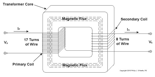
Figure 2 – Basic Transformer Example We can see that the primary coil has 17 turns of wire and the secondary coil has 8. For purposes of our example and to keep the numbers workable, let’s arbitrarily say that VP = 5 volts AC. By the way, the power initially coming into the transformer feeding your home is typically measured in the thousands of volts. Now it’s time to do some math. Based on this input voltage and the number of wire turns in each coil, what would the voltage be on the secondary coil? As William Stanley discovered, it’s a matter of ratios and algebra, and it works according to this formula: NP ÷ NS = VP ÷ VS Here NP and NS are the number of turns of wire in the primary and secondary coils, respectively. So plugging in the numbers we get: 17 turns ÷ 8 turns = 5 volts ÷ VS [(8 turns ÷ 17 turns) x 5 volts] = VS = 2.3 volts This tells us that the transformer in our example reduces, or “steps down” 5 volts AC to just under half the voltage. So the transformer changed a higher voltage to a lower voltage. By the same token, a large utility transformer can be used to reduce transmission line voltage to one which can be used safely within our homes. Like magic, this mechanism also works in reverse. For example, you can apply 2.3volts AC to the 8 turn coil and you will get 5 volts AC out of the 17 turn coil, resulting in a “stepping up” of voltage. But wait a minute. How can you possibly get more voltage out than you put in? Next time we’ll find out. _____________________________________________
|

Transformers – Alternating Current Does the Trick
Sunday, December 12th, 2010| If you’ve seen the movie The Prestige, you know just how “tricky” electricity can be, and if you haven’t seen it yet, you’ve yet to see a great movie. In it, Hugh Jackman uses the magical properties of electricity to pull off a magic trick the likes of which the world has never seen. But that’s all I’ll say about that… see the movie.
In 1886, a young American inventor named William Stanley did some serious thinking about Michael Faraday, the British scientist we introduced last week, and his work with electricity and magnetism. Stanley figured out how to put it all together. The result was the world’s first electrical transformer. What fueled Stanley’s curiosity? Like most good inventors, he perceived a need and sought to fill it. At the time George Westinghouse was developing his alternating current (AC) electric utility power system, the same basic system we use today. As Westinghouse’s chief engineer, Stanley was given the task of figuring out a way to efficiently change voltage levels on an AC power grid. The industrial revolution was in full swing, and for various industrial purposes factories needed to operate on voltage levels different from those produced by the Westinghouse generators. Stanley approached the task before him with the benefit of knowledge supplied by Faraday’s experimentation. He knew that Faraday was able to cause current to flow through a wire by moving a magnet near it back and forth. This phenomenon occurred because lines of magnetic flux were varying over time with respect to the wire through the magnet’s movement. Being aware of the vicissitudes of alternating current, the way it varies in intensity and direction, Stanley was able to conclude that any lines of magnetic flux generated by AC current flowing through a coiled wire would also tend to vary over time. Armed with this knowledge, Stanley replaced the DC battery used in Faraday’s experiment with an AC generator. This modified setup is shown in Figure 1.
Figure 1 – Faraday’s Experiment Modified With An AC Power Source In the modified setup the switch is closed, causing the AC power flowing through the first coiled wire to create lines of magnetic flux in the iron rod. These lines of flux continually vary and thus induce AC flow in the second coil. The action taking place is duly recorded by a Galvanometer needle, which keeps moving so long as the switch remains closed. Stanley also knew that the voltage created in the second coiled wire was dependent on how many turns, or loops, of wire were present in it compared to the number of turns of wire in the first coil. He made the observation that if less turns were present in the second coiled wire as compared to the first, less voltage would also be emitted from the second coiled wire. This demonstrates the phenomenon of changing voltage with respect to supply delivered by the AC generator to the first coil. Putting these findings together, Stanley was able to develop the first practical electrical transformer, whose basic design is shown in Figure 2. Here we see that the iron rod from Faraday’s experiment has been replaced with an iron transformer core resembling a squared off doughnut.
Figure 2 – A Basic Electrical Transformer Next time we’ll get into the math behind this discussion, and we’ll see how Stanley’s transformer worked. _____________________________________________ |
Dynamic Brakes
Monday, May 31st, 2010|
Last week we looked at how a mechanical brake stopped a rotating wheel by converting its mechanical energy, namely kinetic energy, into heat energy. This week, we’ll see how a dynamic brake works. Chances are you have directly benefited by a dynamic braking system the last time you rode in an elevator. But, to understand the basic principle behind an elevator’s dynamic brake system, let’s first take a look at the electric braking system in Figure 1 below.
Figure 1 – A Simple Electric Braking System Here the brake consists of an electric generator wired via an open switch to an electrical component called a resistor. The weight is attached to a cable that is wound around a pulley on the generator’s shaft. As the weight freefalls, the cable unwinds on the pulley, causing the pulley to turn the generator’s shaft. Unlike last week’s mechanical brake which required a good deal of effort to employ, a dynamic braking system requires very little. All that needs to be done is to close a switch as shown in Figure 2 below. When the switch is closed, an electrical circuit is created where the resistor gets connected to the generator. The resistor does as its name implies: it resists (but doesn’t stop) the electrical current flowing through it from the generator. As the electrical current fights its way through the resistor to get back to the generator, the resistor gets hot like an electric heater. This heat is dissipated to the cooler surrounding air. At the same time, the weight begins to slow down in its descent. But how is this happening? The electric braking system can be thought of as an energy conversion process. We start out with the kinetic, or motion energy, of the freefalling weight. This kinetic energy is transmitted to the electrical generator by the cable, which spins the generator’s shaft as the cable unwinds. Electrical generators are machines that convert kinetic energy into electrical energy. This energy travels from the electric generator through wires and a closed switch to the resistor. In the process the resistor converts the electrical energy into heat energy. So, kinetic energy is drawn from the falling weight through the conversion process and leaves the process in the form of heat. As the falling weight is drained of kinetic energy, it slows down.
Figure 2 – Applying the Electric Brake Okay, now let’s get back to dynamic brakes on elevators. An elevator is attached by a cable to a hoist that is powered by an electric motor. When it’s time to stop at the desired floor, the automatic control system disconnects the elevator’s electric motor from its power source and turns the motor into a generator. The generator is then automatically connected to a resistor like the one shown in the electric brake above. The kinetic energy of the moving elevator is converted by the generator into electrical energy. The resistor converts the electrical energy into heat energy which is then dissipated into the surrounding environment. The elevator slows down in the process because it’s being robbed of kinetic energy. When the dynamic brake slows the elevator down enough, a mechanical brake is introduced, taking over to bring the elevator to a complete stop. This two-fold process serves to reduce wear and tear on the mechanical brake’s parts, lengthening the operational lifespan of the system as a whole. Next time, we’ll tie everything together and show how mechanical and dynamic brakes work together in a diesel locomotive. _____________________________________________
|


Wind Turbine Energy, Is It The Answer?
Sunday, April 4th, 2010|
Alternative energy is a hot topic today. There are certainly benefits to be gained by replacing fossil fueled power plants with alternative energy sources. One of the most publicized of these is the free energy that is generated by wind turbines that drive electric generators. Surely this is a win-win situation? Let’s take a closer look! If you’ve been out in the country within the last few years you’ve surely seen the new generation of windmill. These mammoths are so large and intimidating they remind me of the cartoon robot, Gigantor, popular back in the 1960s—scary until you get to know him. Yes, these wind turbines are big, and so is their cost. They are so expensive that a return on investment is a rather long way off. Let’s examine the numbers. A 2 megawatt wind turbine can cost over $2 million to purchase and install. By 2 megawatt, I mean two million watts of output. The generator on this baby can produce enough power to light around 33,330 sixty watt bulbs. If I were to install one on my property, my local electric utility would be willing to pay me approximately $10,000 per month to buy its power from me. At this rate of compensation, it would take over 16 years to realize a return on my investment. That’s the “looks good on paper” figure. Realistically speaking, it would actually take a lot longer than 16 years if we factor in the cost of maintenance and the interest rates on borrowed money. So what happens if the Gigantor in your back yard needs servicing? I did some checking, and it’s not cheap. It can cost as much as $15,000 just to hire the massive crane that is required to lift the heavy parts involved. Aside from purchase price and maintenance expenses, another thing to consider when talking installation of wind turbines is the fact that they operate at the mercy of Mother Nature. No wind, no power. Is there anything we can do to compensate for this factor, like store the energy generated on a windy day for future usage? This would be a great solution, if only battery technology was economical enough for storage of the vast amounts of energy that is required to power an electric utility grid if the wind stops blowing for an extended period of time. For example, sodium battery technology is up to the task, but the cost is high, at around $3,500.00 per kilowatt-hour. At this price a 2 megawatt wind turbine would need about $7 million worth of storage just to get us through about one hour of calm weather! Now here’s a proposed solution to the storage issue that you may have read about. It involves utilizing storage systems which would use electric motors to convert the electrical energy from the turbine generators into mechanical energy. This energy would then be transferred to mechanical storage devices, such as a huge flywheel. Then, if the wind stops blowing and power stops flowing, the motor on the flywheel can be turned into an electric generator. The mechanical energy stored in its spinning mass would power the generator, which would in turn keep electricity flowing into the power grid. Now remember, the amount of mechanical energy we can store in a flywheel spinning at a given speed depends on its mass, that is, how heavy it is. The more energy we have to store, the heavier the flywheel has to be. So when we’re talking about storing many millions of watts of energy to get us through several days of calm weather, we’d have to make a flywheel so massive it would be impractical and uneconomical to build. Just to store about one hour’s worth of energy from our 2-megawatt wind turbine we’d need to build a flywheel over 65 feet in diameter that spins at 1800 rpm and weighs more than 9 tons. Another proposal to store the wind turbine’s energy involves the use of electric motors to drive air compressors that would pressurize caverns deep below the earth’s surface. This effectively creates what is called a compressed-air energy storage (CAES) facility. The idea here is that when the wind stops, the motors would act as generators and the compressors would act as air turbines. This pressurized air could then be drained from the caverns in which it is stored and redirected to flow through the turbine. Then, finally, the stored mechanical energy in the pressurized air would be converted by the air turbine and generator back into electrical energy to power the grid. At best, a CAES facility will run at about 70% efficiency. That means for every 100 kilowatt-hours of energy you put into storage, you only receive 70 kilowatt-hours in return. Once examined, it seems that current technology does not provide a cost-feasible solution for the replacement of fossil fuel backed energy with wind turbine energy. So where do we go from here? We’ll continue our exploration of alternative energy next week. _________________________________________________________________
|


