| If you’ve seen the movie The Prestige, you know just how “tricky” electricity can be, and if you haven’t seen it yet, you’ve yet to see a great movie. In it, Hugh Jackman uses the magical properties of electricity to pull off a magic trick the likes of which the world has never seen. But that’s all I’ll say about that… see the movie.
In 1886, a young American inventor named William Stanley did some serious thinking about Michael Faraday, the British scientist we introduced last week, and his work with electricity and magnetism. Stanley figured out how to put it all together. The result was the world’s first electrical transformer. What fueled Stanley’s curiosity? Like most good inventors, he perceived a need and sought to fill it. At the time George Westinghouse was developing his alternating current (AC) electric utility power system, the same basic system we use today. As Westinghouse’s chief engineer, Stanley was given the task of figuring out a way to efficiently change voltage levels on an AC power grid. The industrial revolution was in full swing, and for various industrial purposes factories needed to operate on voltage levels different from those produced by the Westinghouse generators. Stanley approached the task before him with the benefit of knowledge supplied by Faraday’s experimentation. He knew that Faraday was able to cause current to flow through a wire by moving a magnet near it back and forth. This phenomenon occurred because lines of magnetic flux were varying over time with respect to the wire through the magnet’s movement. Being aware of the vicissitudes of alternating current, the way it varies in intensity and direction, Stanley was able to conclude that any lines of magnetic flux generated by AC current flowing through a coiled wire would also tend to vary over time. Armed with this knowledge, Stanley replaced the DC battery used in Faraday’s experiment with an AC generator. This modified setup is shown in Figure 1.
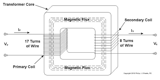
Figure 1 – Faraday’s Experiment Modified With An AC Power Source In the modified setup the switch is closed, causing the AC power flowing through the first coiled wire to create lines of magnetic flux in the iron rod. These lines of flux continually vary and thus induce AC flow in the second coil. The action taking place is duly recorded by a Galvanometer needle, which keeps moving so long as the switch remains closed. Stanley also knew that the voltage created in the second coiled wire was dependent on how many turns, or loops, of wire were present in it compared to the number of turns of wire in the first coil. He made the observation that if less turns were present in the second coiled wire as compared to the first, less voltage would also be emitted from the second coiled wire. This demonstrates the phenomenon of changing voltage with respect to supply delivered by the AC generator to the first coil. Putting these findings together, Stanley was able to develop the first practical electrical transformer, whose basic design is shown in Figure 2. Here we see that the iron rod from Faraday’s experiment has been replaced with an iron transformer core resembling a squared off doughnut.
Figure 2 – A Basic Electrical Transformer Next time we’ll get into the math behind this discussion, and we’ll see how Stanley’s transformer worked. _____________________________________________ |
Posts Tagged ‘Faraday’s experiment’
Transformers – Alternating Current Does the Trick
Sunday, December 12th, 2010Transformers and The Magic of Electricity
Sunday, December 5th, 2010| No, the next series of articles is not about those talking, morphing, gigantic killing machines that children love to play with. We’re going to talk about the type that adults just can’t live without.
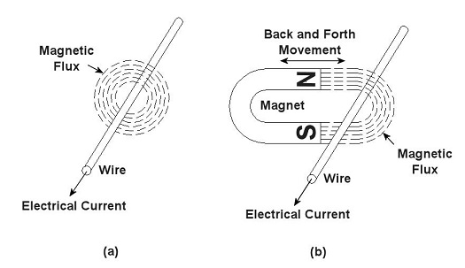
You’ve probably heard the term “electrical transformer” at some point, but you may not be entirely sure what is meant by it. Most don’t realize that they use them all the time, like when they recharge their cell phone battery. That little black box that plugs into the wall outlet is one of them, and what they do is perform the important task of reducing the 120 volts of power that fuels your home’s outlets down to a lower voltage level, for example, 12 volts, which can be used by small electronic devices. But before I explain how this reduction process works we need to understand magnets. Magnets, those wonderful curiosities that mesmerized you as a kid, keeping you busy for hours picking up nails and paper clips, have many practical applications, although they weren’t considered to be anything more than amusing novelties until the early 19th Century. That’s when a French scientist by the name of André-Marie Ampére studied the relationship between magnetism and electricity. What he found was that when an electrical current is run through a wire it turns into a magnet. Ampere’s work was then built upon by British scientist Michael Faraday. He discovered that electric current passing through wire creates magnetic lines of flux that encircle the wire as shown in Figure 1 (a). Faraday also discovered that if you move a magnet back and forth near a wire, as shown in Figure 1 (b), you can generate an electrical current in the wire.
Figure 1 – Relationships Between Electricity and Magnetism Why does this happen? Well, magnets work as they do because they have a magnetic north (N) and south (S) pole, and lines of magnetic flux extend from one pole to the other. You can actually see these lines of flux if you sprinkle iron filings between the poles. The iron filings are attracted to the magnet and align themselves along the lines as shown in Figure 2. When the lines of flux move through the wire, they induce an electrical current in it. As long as you keep the magnet moving back and forth, lines of flux will continue to pass through the wire, and the current will keep flowing. When the magnet stops moving, the current in the wire also stops.
Figure 2 – Iron Filings Aligned Along Lines of Magnetic Flux Faraday soon began experimenting with coiled wires and iron rods. He wanted to see how electrical current flowing through one coiled wire would affect another coiled wire in close proximity. His basic experimental setup is shown in Figure 3.
Figure 3 – Michael Faraday’s Experiment Faraday’s experiment consisted of two insulated wires, each coiled around an iron rod. The first coiled wire ran to a battery and then a switch. The switch enabled Faraday to connect and disconnect the battery to the first coil during his experiments. The second coiled wire was connected to an instrument called a Galvanometer, which measures the amount of electricity flowing through the wire. When the switch was closed, connecting the first coil to the battery, Faraday noticed that the Galvanometer’s indicator needle moved, then returned to zero. Somehow the electricity flowing from the battery to the first coil was causing an electric current to momentarily flow in the second coil. But how does electricity flow from one coil to the other if they’re not connected? It doesn’t. What’s actually taking place is known as “electromagnetic induction.” Faraday’s experiment enabled him to conclude that current flowing through the first coil set up lines of magnetic flux in the iron rod to which both coiled wires were attached. When the switch was closed, the lines of magnetic flux built in intensity until they induced a current in the second coil. But when the magnetic flux reached its full intensity, and stayed at full intensity, the current induced in the second coil stopped flowing. Faraday’s initial confusion as to the state of affairs soon changed into the Eureka! moment of discovery, and he was able to conclude that current will flow in the second coil only if the lines of magnetic flux are fluctuating in intensity. Next week we’ll see how an as yet undiscovered young inventor used the results of Faraday’s experiment to build the first electrical transformer. _____________________________________________ |


