| When I had the misfortune of getting stuck in my Uncle Jake’s outhouse as a kid, I would allow my hysteria to get the best of me and forget my uncle’s instructions on how to get out. It was a series of raps and a single kick that would prove to be the magic formula, and once I had calmed myself down enough to employ them I would succeed in working the door’s rusty latch open. Our relay circuit below has a much less challenging system to effectively unlatch the pattern of electric current.
Figure 1 shows our latched circuit, where red lines denote the flow of current.
Figure 1
If you recall, the relay in this circuit was latched by pressing Pushbutton 1. When in the latched state, the magnetic attraction maintained by the wire coil and steel core won’t allow the relay armatures to release from their N.O. contacts. The relay’s wire coil stays energized via Button 2, the red bulb goes dark while the green bulb remains lit, even though Button 1 is no longer actively depressed. Now let’s take a look at Figure 2 to see how to get the circuit back to its unlatched state.
Figure 2
With Button 2 depressed the flow of current is interrupted and the relay’s wire coil becomes de-energized. In this state the coil and steel core are no longer magnetized, causing them to release their grip on the steel armatures. The spring will now pull them back until one of them makes contact with the N.C. contact. The red bulb lights again, although Button 2 is not being actively depressed. At this point the electric relay has become unlatched. It can be re-latched by depressing Button 1 again. Let’s see how we can simplify Figure 2’s representation with a ladder diagram, as shown in Figure 3.
Figure 3
We’ve seen how this latching circuit activates and deactivates bulbs. Next time we’ll see how it controls an electric motor and conveyor belt inside a factory. ____________________________________________ |
Posts Tagged ‘magnetism’


Transformers and The Magic of Electricity
Sunday, December 5th, 2010| No, the next series of articles is not about those talking, morphing, gigantic killing machines that children love to play with. We’re going to talk about the type that adults just can’t live without.
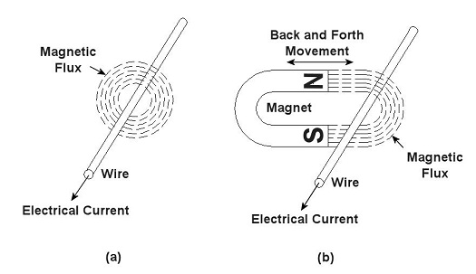
You’ve probably heard the term “electrical transformer” at some point, but you may not be entirely sure what is meant by it. Most don’t realize that they use them all the time, like when they recharge their cell phone battery. That little black box that plugs into the wall outlet is one of them, and what they do is perform the important task of reducing the 120 volts of power that fuels your home’s outlets down to a lower voltage level, for example, 12 volts, which can be used by small electronic devices. But before I explain how this reduction process works we need to understand magnets. Magnets, those wonderful curiosities that mesmerized you as a kid, keeping you busy for hours picking up nails and paper clips, have many practical applications, although they weren’t considered to be anything more than amusing novelties until the early 19th Century. That’s when a French scientist by the name of André-Marie Ampére studied the relationship between magnetism and electricity. What he found was that when an electrical current is run through a wire it turns into a magnet. Ampere’s work was then built upon by British scientist Michael Faraday. He discovered that electric current passing through wire creates magnetic lines of flux that encircle the wire as shown in Figure 1 (a). Faraday also discovered that if you move a magnet back and forth near a wire, as shown in Figure 1 (b), you can generate an electrical current in the wire.
Figure 1 – Relationships Between Electricity and Magnetism Why does this happen? Well, magnets work as they do because they have a magnetic north (N) and south (S) pole, and lines of magnetic flux extend from one pole to the other. You can actually see these lines of flux if you sprinkle iron filings between the poles. The iron filings are attracted to the magnet and align themselves along the lines as shown in Figure 2. When the lines of flux move through the wire, they induce an electrical current in it. As long as you keep the magnet moving back and forth, lines of flux will continue to pass through the wire, and the current will keep flowing. When the magnet stops moving, the current in the wire also stops.
Figure 2 – Iron Filings Aligned Along Lines of Magnetic Flux Faraday soon began experimenting with coiled wires and iron rods. He wanted to see how electrical current flowing through one coiled wire would affect another coiled wire in close proximity. His basic experimental setup is shown in Figure 3.
Figure 3 – Michael Faraday’s Experiment Faraday’s experiment consisted of two insulated wires, each coiled around an iron rod. The first coiled wire ran to a battery and then a switch. The switch enabled Faraday to connect and disconnect the battery to the first coil during his experiments. The second coiled wire was connected to an instrument called a Galvanometer, which measures the amount of electricity flowing through the wire. When the switch was closed, connecting the first coil to the battery, Faraday noticed that the Galvanometer’s indicator needle moved, then returned to zero. Somehow the electricity flowing from the battery to the first coil was causing an electric current to momentarily flow in the second coil. But how does electricity flow from one coil to the other if they’re not connected? It doesn’t. What’s actually taking place is known as “electromagnetic induction.” Faraday’s experiment enabled him to conclude that current flowing through the first coil set up lines of magnetic flux in the iron rod to which both coiled wires were attached. When the switch was closed, the lines of magnetic flux built in intensity until they induced a current in the second coil. But when the magnetic flux reached its full intensity, and stayed at full intensity, the current induced in the second coil stopped flowing. Faraday’s initial confusion as to the state of affairs soon changed into the Eureka! moment of discovery, and he was able to conclude that current will flow in the second coil only if the lines of magnetic flux are fluctuating in intensity. Next week we’ll see how an as yet undiscovered young inventor used the results of Faraday’s experiment to build the first electrical transformer. _____________________________________________ |


