| When my daughter was seven she found out about Ohm’s Law the hard way, although she didn’t know it. She had accidentally bumped into her electric toy train, causing its metal wheels to derail and fall askew of the metal track. This created a short circuit, causing current to flow in an undesirable direction, that is, through the derailed wheels rather than along the track to the electric motor in the locomotive as it should.
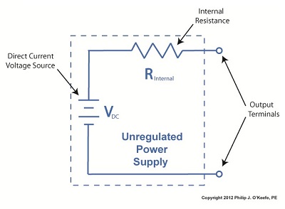
What happened during the short circuit is that the bulk of the current began to follow through the path of least resistance, that of the derailed wheels, rather than the higher resistance of the electric motor. Electric current, always opportunistic, will flow along its easiest course, in this case the short, thick metal of the wheels, rather than work its way along the many feet of thin metal wire of the motor’s electromagnetic coils. With its wheels sparking at the site of derailment the train had become an electric toaster within seconds, and the carpet beneath the track began to burn. Needless to say, mom wasn’t very happy. In this instance Ohm’s Law was at work, with a decidedly negative outcome. The Law’s basic formula concerning the toy train would be written as: I = V ÷ Rwhere, I is the current flowing through the metal track, V is the track voltage, and R is the internal resistance of the metal track and locomotive motor, or in the case of a derailment, the metal track and the derailed wheel. So, according to the formula, for a given voltage V, when the R got really small due to the derailment, I got really big. But enough about toy trains. Let’s see how Ohm’s Law applies to an unregulated power supply circuit. We’ll start with a schematic of the power supply in isolation. Figure 1The unregulated power supply shown in Figure 1 has two basic aspects to its operation, contained within a blue dashed line. The dashed line is for the sake of clarity when we connect the power supply up to an external circuit which powers peripheral devices later on. The first aspect of the power supply is a direct current (DC) voltage source, which we’ll call VDC. It’s represented by a series of parallel lines of alternating lengths, a common representation within electrical engineering. And like all electrical components, the power supply has an internal resistance, such as discussed previously. This resistance, notated RInternal, is the second aspect of the power supply, represented by another standard symbol, that of a zigzag line. Finally, the unregulated power supply has two output terminals. These will connect to an external supply circuit through which power will be provided to peripheral devices. Next time we’ll connect to this external circuit, which for our purposes will consist of an electric relay, buzzer, and light to see how it all works in accordance with Ohm’s Law. ____________________________________________ |
Posts Tagged ‘electrical engineering’
Just Call Me Expert
Sunday, June 12th, 2011| Last week I said we’d talk about ground fault circuit interrupters (GFCI), but before we get to that let me provide a little background on how I recently came to be a subject matter expert for The Discovery Channel.
The program I was asked to contribute to is titled, “Curious and Unusual Deaths,” where I will be discussing a variety of tragic occurrences, including deaths by electrocution. It’s actually slotted to be a series of half-hour segments presenting, you got it, some of the strangest, most grizzly, tragic, or simply avoidable deaths from across the globe and throughout time. The episodes use actors to recreate the incidents, which take place in a variety of locations, from the home to the workplace. After presenting a graphic portrayal of the unfortunate event, experts, including myself, provide an explanation of the science behind it all. Cinematic recreations and high quality computer generated imagery are used to recreate how the deaths occurred as well as illustrate the experts’ explanations. It all started when I was contacted by a researcher for the program. She had discovered me through this very blog site, the Engineering Expert Witness Blog, and was impressed with my diverse background, which as my loyal readers know covers both mechanical and electrical engineering. She also liked the fact that I’ve worked professionally within many different industries. Needless to say, I was flattered. She went on to explain that she was interested in discussing with me the technical aspects of four particularly unusual but actual incidents that had proven to be deadly to those involved in them. The deaths were due to a variety of factors, from a steam pipe failure, to contacting high voltage electronics through a seemingly benign unplugged appliance, to succumbing to carbon monoxide poisoning produced by a propane heater, and finally, the one I thought to be most unusual of all, a death caused by touching a hotel room door that was, unbeknownst to the person inserting the key in the lock, charged with stray electrical current from an unlikely source. Sound interesting? Look for the series to air in the near future to find out more. We discussed the incidents by phone for awhile, and then a week later I received another call inviting me to fly up to Toronto, Canada, to be videotaped as an expert for the series. Now, although I do not have a ham bone in my body, I do enjoy sharing my knowledge of technical things with others, so I gladly took her up on the offer. Tune in next week to read the insider’s track on the making of a quality television series. _____________________________________________ |


