Posts Tagged ‘voltage source’

The Solenoid Valve’s Components

Monday, July 23rd, 2018

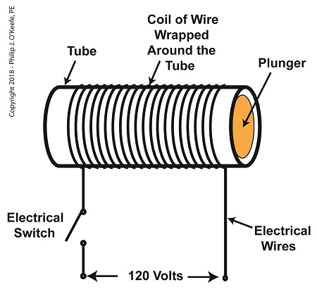
    So far in this series of articles, we have talked about pneumatic actuators that move jelly filling through a depositor on a pastry production line in a food manufacturing plant.   These actuators have pistons with piston rods that create linear motion.   The direction of this motion depends on which side compressed air is admitted to the piston inside the actuator.   Now, let’s begin discussing a device known to engineers as a solenoid valve.   These valves are used to selectively admit compressed air to either side of the pneumatic actuator’s piston, and thus, change the direction of the actuator’s linear motion.

    As a solenoid valve’s name implies, a key component is a solenoid.   A solenoid consists of a tube, having a coil of wire wrapped around its exterior.   Electrical wires extend from the coil to an electrical switch and a voltage supply of, for example, 120 Volts.   Inside the tube, there is a steel plunger that is free to move.    When the switch is open, the coil is de-energized.   That is, no electric current flows from the voltage supply through the coil of wire.

 A De-Energized Solenoid

A De-Energized Solenoid


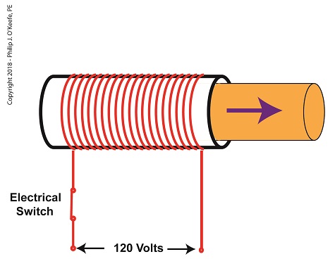
    When the electrical switch is closed, the coil becomes energized. As electrical current flows through the coil, a magnetic field is created in the tube.   This field forces the steel plunger out of the tube.  The magnetic field and force on the plunger remain as long as the switch is closed.

An Energized Solenoid

An Energized Solenoid


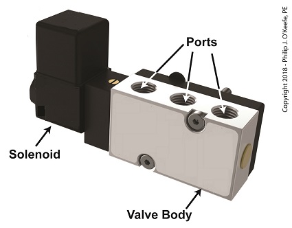
    A solenoid valve consists of a solenoid that is attached to a metal valve body.   The solenoid is typically enclosed in a plastic or metal housing.   The valve body contains various ports.   The ports are threaded holes for the connection of compressed air pipes.

A Solenoid Valve

A Solenoid Valve


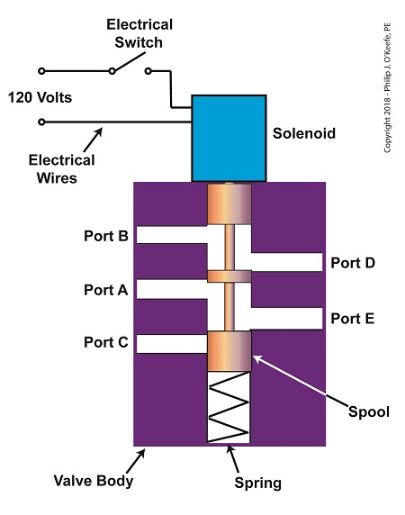
    The solenoid’s plunger is attached to spool in the valve body.   The spool is free to move within the valve body past passage ways extending from the ports.   In the following illustration, the solenoid valve contains five ports, designated A through E.


The Solenoid Valve’s Components

The Solenoid Valve’s Components


    Next time we’ll see how the five port solenoid valve operates to create different compressed air flow paths between its ports.


Copyright 2018 – Philip J. O’Keefe, PE

Engineering Expert Witness Blog

____________________________________


Transistors – Voltage Regulation Part VI

Sunday, August 26th, 2012
     Believe it or not as a kid in grade school I used to hate math, particularly algebra.  None of my teachers were able to decipher its complexities and render it comprehensible to me or the majority of my classmates.  Then in high school everything changed.  I had Mr. Coleman for freshman algebra, and he had a way of making it both understandable and fun, in a challenging kind of way.  With 40 years of teaching under his belt, Mr. Coleman knew exactly how to convey the required information in an understandable manner, and to this day I find his insights useful in solving engineering calculations.

      Last time we began our discussion on Ohm’s Law and how it may be applied to our example circuit to solve for the electrical current flowing through it.  Let’s continue our discussion to see how the Law applies to only one part of the circuit.  Then, we’ll use a little algebra to show how the output voltage of an unregulated power supply is affected by changes in RTotal.

electronic power supply

Figure 1


     To help us see things more clearly, in Figure 1 we’ll cover up the inside workings of the unregulated power supply side of the circuit and concentrate on the external supply part of the circuit alone.  Since RTotal is connected to the terminals of the power supply, the voltage applied to RTotal is the same as the power supply output voltage, VOutput.

     In my previous article, we learned that according to Ohm’s Law, the current flowing through a resistance is equal to the voltage applied to it, divided by the resistance.  The fact that RTotal is connected to the two output terminals like we see in Figure 1, allows us to use Ohm’s law to solve for the electrical current, I, flowing through  RTotal:

I = VOutput ÷ RTotal

     Now let’s pull the cover off of the unregulated power supply again to see what’s going on within the circuit as a whole.

electronic circuit

Figure 2


    In Figure 2 we can see that the current, I, flowing through RTotal is the same current flowing through the balance of the circuit.  In the preceding blog we found that value to be:

I = VDC ÷ (RInternal + RTotal)

     We can combine the above two equations for I to develop an algebraic relationship between VOutput and RInternal, RTotal, and VDC:

VOutput ÷ RTotal   =  VDC ÷ (RInternal + RTotal)

     Then, by rearranging terms and applying the cross multiplication principle of algebra we can solve for VOutput.  This involves multiplying both sides of the equation by RTotal:

VOutput =  RTotal × (VDC ÷ (RInternal +RTotal))

     This equation tells us that although RInternal doesn’t fluctuate, VOutput will fluctuate when RTotal does.  This fact is demonstrated in our equation when we make use of algebra.  That is to say, when a term changes on one side of the equation, it causes the other side of the equation to change as well.  In this case, when RTotal  changes, it causes VOutput to change in proportion to the fixed values of VDC and RInternal.

     Next time we’ll look at another shortcoming of unregulated power supplies, more specifically, how one supply can’t power multiple electrical circuits comprised of different voltages. 

____________________________________________

Transistors – Voltage Regulation Part III

Tuesday, August 7th, 2012
     When my daughter was seven she found out about Ohm’s Law the hard way, although she didn’t know it.  She had accidentally bumped into her electric toy train, causing its metal wheels to derail and fall askew of the metal track.  This created a short circuit, causing current to flow in an undesirable direction, that is, through the derailed wheels rather than along the track to the electric motor in the locomotive as it should.

    What happened during the short circuit is that the bulk of the current began to follow through the path of least resistance, that of the derailed wheels, rather than the higher resistance of the electric motor.  Electric current, always opportunistic, will flow along its easiest course, in this case the short, thick metal of the wheels, rather than work its way along the many feet of thin metal wire of the motor’s electromagnetic coils.  With its wheels sparking at the site of derailment the train had become an electric toaster within seconds, and the carpet beneath the track began to burn.  Needless to say, mom wasn’t very happy.

     In this instance Ohm’s Law was at work, with a decidedly negative outcome.  The Law’s basic formula concerning the toy train would be written as:

I = V ÷ R

where, I is the current flowing through the metal track, V is the track voltage, and R is the internal resistance of the metal track and locomotive motor, or in the case of a derailment, the metal track and the derailed wheel.  So, according to the formula, for a given voltage V, when the R got really small due to the derailment, I got really big.

     But enough about toy trains.  Let’s see how Ohm’s Law applies to an unregulated power supply circuit.  We’ll start with a schematic of the power supply in isolation.

Figure 1

     The unregulated power supply shown in Figure 1 has two basic aspects to its operation, contained within a blue dashed line.  The dashed line is for the sake of clarity when we connect the power supply up to an external circuit which powers peripheral devices later on.  The first aspect of the power supply is a direct current (DC) voltage source, which we’ll call VDC.  It’s represented by a series of parallel lines of alternating lengths, a common representation within electrical engineering.

     And like all electrical components, the power supply has an internal resistance, such as discussed previously.  This resistance, notated RInternal, is the second aspect of the power supply, represented   by another standard symbol, that of a zigzag line.

     Finally, the unregulated power supply has two output terminals.  These will connect to an external supply circuit through which power will be provided to peripheral devices.  Next time we’ll connect to this external circuit, which for our purposes will consist of an electric relay, buzzer, and light to see how it all works in accordance with Ohm’s Law.

____________________________________________