Posts Tagged ‘magnetic field’
Monday, July 30th, 2018
|
Previously, we looked at the components of a solenoid valve, which is an electro-mechanical device that is commonly used by engineers to operate pneumatic actuators with compressed air. These solenoid valve components include a solenoid and a valve body. We also looked at an illustration of an example solenoid valve. Its valve body had five ports for connections to compressed air pipes. Now, let’s see how the example solenoid valve operates to create different compressed air flow paths between its ports.
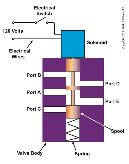
When the solenoid valve’s electrical switch is opened, the flow of electrical current from its 120 Volt supply is interrupted. This results in the solenoid’s wire coil being de-energized. As such, the coil generates no magnetic field. Without the magnetic field, there is no downward force exerted on the solenoid’s plunger and the valve body’s spool. A spring at the bottom of the valve body acts upon the spool to force it upward in the valve body and hold it there. With the spool in the upward position, two compressed air flow paths are created in the valve body. One path extends through a passageway connecting Ports D and B, and the other extends through a passageway connecting Ports A and E. The spool seals off the passageway leading to Port C.
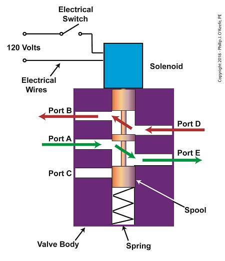
The Solenoid Valve’s Operation: De-energized
When the electrical switch is closed, the 120 Volt supply is connected to the valve’s solenoid. This results in the solenoid’s coil becoming energized. When that happens, the electrical current flowing through the coil generates a magnetic field. The magnetic field forces the plunger and spool in the downward direction. The spool overcomes the spring force and moves into a downward position within the valve body. In this position, the spool creates a new pair of compressed air flow paths. These paths remain as long as the current flows through the solenoid’s coil. One compressed air flow path extends between Ports A and D. The other path extends between Ports E and C. The spool seals off the passageway leading to Port B.

The Solenoid Valve’s Operation: Energized
When the electrical switch opens, the solenoid’ coil again becomes de-energized. The magnetic field collapses, and no downward force remains on the plunger and spool. The spring forces the spool back up in the valve body. Once again, a pair of compressed air flow paths is created between Ports D and B, and between Ports A and E. The passageway to Port C is sealed off by the spool.
Next time, we’ll see how the example solenoid valve’s operation is applied to move the piston back and forth in a depositor’s pneumatic actuator.
Copyright 2018 – Philip J. O’Keefe, PE
Engineering Expert Witness Blog
____________________________________ |
Tags: air flow path, compressed air, depositor, engineering, magnetic field, plunger, pneumatic actuator, ports, solenoid, solenoid valve, spool, valve body
Posted in Engineering and Science, Expert Witness, Forensic Engineering, Innovation and Intellectual Property, Personal Injury, Product Liability | Comments Off on The Solenoid Valve’s Operation
Monday, July 23rd, 2018
|
So far in this series of articles, we have talked about pneumatic actuators that move jelly filling through a depositor on a pastry production line in a food manufacturing plant. These actuators have pistons with piston rods that create linear motion. The direction of this motion depends on which side compressed air is admitted to the piston inside the actuator. Now, let’s begin discussing a device known to engineers as a solenoid valve. These valves are used to selectively admit compressed air to either side of the pneumatic actuator’s piston, and thus, change the direction of the actuator’s linear motion.
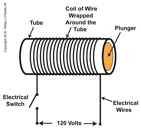
As a solenoid valve’s name implies, a key component is a solenoid. A solenoid consists of a tube, having a coil of wire wrapped around its exterior. Electrical wires extend from the coil to an electrical switch and a voltage supply of, for example, 120 Volts. Inside the tube, there is a steel plunger that is free to move. When the switch is open, the coil is de-energized. That is, no electric current flows from the voltage supply through the coil of wire.
A De-Energized Solenoid
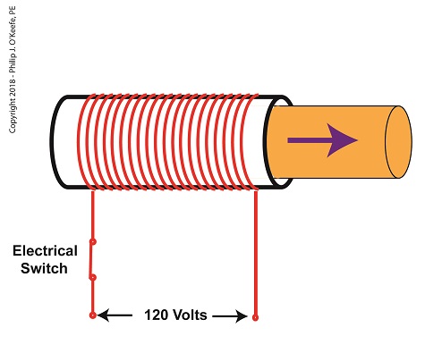
When the electrical switch is closed, the coil becomes energized. As electrical current flows through the coil, a magnetic field is created in the tube. This field forces the steel plunger out of the tube. The magnetic field and force on the plunger remain as long as the switch is closed.
An Energized Solenoid
A solenoid valve consists of a solenoid that is attached to a metal valve body. The solenoid is typically enclosed in a plastic or metal housing. The valve body contains various ports. The ports are threaded holes for the connection of compressed air pipes.
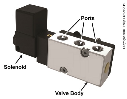
A Solenoid Valve
The solenoid’s plunger is attached to spool in the valve body. The spool is free to move within the valve body past passage ways extending from the ports. In the following illustration, the solenoid valve contains five ports, designated A through E.
The Solenoid Valve’s Components
Next time we’ll see how the five port solenoid valve operates to create different compressed air flow paths between its ports.
Copyright 2018 – Philip J. O’Keefe, PE
Engineering Expert Witness Blog
____________________________________ |
Tags: coil, compressed air, depositor, engineers, food manufacturing, jelly filling, magnetic field, pastry line, plunger, port, solenoid, solenoid valve, spool, switch, valve body, voltage source
Posted in Engineering and Science, Expert Witness, Forensic Engineering, Innovation and Intellectual Property, Personal Injury, Product Liability, Professional Malpractice | Comments Off on The Solenoid Valve’s Components
Friday, October 16th, 2015
|
In my work as an engineering expert I’ve dealt with all forms of energy, just as we’ve watched James Prescott Joule do. He constructed his Joule Apparatus specifically to demonstrate the connection between different forms of energy. Today we’ll see how he furthered his discoveries by building a prototype power plant capable of producing electricity, a device which came to be known as Joule’s Experiment With Electricity.

Joule’s Experiment With Electricity
As the son of a wealthy brewer, Joule had been fascinated by electricity and the possibility of using it to power his family’s brewery and thereby boost production. To explore the possibilities, he went beyond the Apparatus he had built earlier and built a device which utilized electricity to power its components. The setup for Joule’s experiment with electricity is shown here.
Coal was used to bring water inside a boiler to boiling point, which produced steam. The steam’s heat energy then flowed to a steam engine, which in turn spun a dynamo, a type of electrical generator.
Tracing the device’s energy conversions back to their roots, we see that chemical energy contained within coal was converted into heat energy when the coal was burned. Heat energy from the burning coal caused the water inside the boiler to rise, producing steam. The steam, which contained abundant amounts of heat energy, was supplied to a steam engine, which then converted the steam’s heat energy into mechanical energy to set the engine’s parts into motion. The engine’s moving parts were coupled to a dynamo by a drive belt, which in turn caused the dynamo to spin.
Next time we’ll take a look inside the dynamo and see how it created electricity and led to another of Joule’s discoveries being named after him.
Copyright 2015 – Philip J. O’Keefe, PE
Engineering Expert Witness Blog
____________________________________ |
Tags: boiler expert witness, dynamo, electric current, electric current induction, electrical energy, electrical engineering expert witness, electrical generator expert witness, electrical resistance of wires, engineering expert witness, forensic engineer, heat energy, James Prescott Joule, Joule Heating Effect, magnetic field, mechanical energy, mechanical engineering expert witness, power engineering expert witness, power plant, power plant engineering expert witness, steam, wire size
Posted in Engineering and Science, Expert Witness, Forensic Engineering, Innovation and Intellectual Property, Personal Injury, power plant training, Product Liability | Comments Off on Joule’s Experiment With Electricity
Monday, March 7th, 2011
| When I was a kid I remember how cool it was to have a headlight on my bike. Unlike the headlights that the other kids had, mine was not powered with flashlight batteries. The power came from a little gadget with a small wheel that rode on the front tire. As I pedaled along, the tire’s spinning caused the small wheel to spin, and voila, the headlight bulb came to life. Little did I know that this gadget was a simple form of electrical generator, and of course I was oblivious to the fact that a similar device, albeit on a much larger scale, was being used at a nearby power plant to send electricity to my home.
Over the last few weeks we learned how a coal fired power plant transforms chemical energy stored in coal into heat energy and then into mechanical energy which enables a steam turbine shaft to spin. We’ll now turn our attention to the electrical generator. It’s responsible for performing the last step in the energy conversion process, that is, it converts mechanical energy from the steam turbine into the desired end product, electrical energy for our use. It represents the culmination in energy’s journey through the power plant, the process by which energy contained in a lump of coal is transformed into electricity.
To show how this final energy conversion process works, let’s look at Figure 1, a simplified illustration of an electrical generator.

Figure 1 – A Basic Electrical Generator
You’ll note that the generator in our illustration has a shaft with a loop of wire attached to it. When the shaft spins, so does the loop. The shaft and wire loop are placed between the north (N) and south (S) poles of a horseshoe magnet. It’s a permanent magnet, so it always has invisible lines of magnetic flux traveling between its two poles. These magnetic lines of flux are the same type as the ones created by kids’ magnets, when they play with watching paperclips jump up to meet the magnet. The properties of magnets are not completely understood, even to adults who work with them every day. And what could be more mysterious than the fact that as the shaft and wire loop spin through the lines of magnetic flux in the generator, an electric current is produced in the wire loop.
Now, this current that’s flowing through the spinning wire loop is of no use if we can’t channel it out of the generator. The wire loop is spinning vigorously, so you can’t directly connect the ends of the loop to stationary wires. A special treatment is required. Each end of the loop is connected to a slip ring. A part called a “brush” presses against each slip ring to make electrical contact. The electrical current then flows from the loop through the spinning slip rings, through the brushes, and into the stationary wires. So, if, for example, a light bulb is connected to the other end of the stationary wires, this completes an electric circuit through which current can flow. The light bulb will glow as long as the generator shaft keeps spinning and the wire loop keeps passing through the magnetic lines of flux from the magnet.
So we see that the key to the whole energy conversion process is to have movement between magnetic lines of flux and a loop of wire. As long as this movement occurs, the electricity will flow. This basic principle is the same in a coal fired power plant, but the electrical generator is far more complicated in construction and operation than shown here. My Coal Power Plant Fundamentals seminar goes into far greater detail on this and other aspects of electricity generation, but what I have shared with you above will give you a basic understanding of how they operate.
That concludes our journal with coal through the power plant. This series of blogs has, you will remember, presented a simplified version of the complex material presented in my teaching seminars. Next week we’ll branch off, taking a look at why electrical wires come in different thicknesses.
_____________________________________________

|
Tags: bicycle, brush, coal power plant fundamentals, electric utility training, electrical energy, electrical generator, electricity from coal, electricty and magnetism, engineering expert witness, flux, forensic engineer, heat energy, lines of flux, magnetic field, mechanical energy, power engineering, power generation, power plant, power plant training, slip ring, steam turbine, training seminar, wire loop
Posted in Engineering and Science, Expert Witness, Forensic Engineering, Innovation and Intellectual Property, Personal Injury, power plant training | Comments Off on Coal Power Plant Fundamentals – The Generator


