|
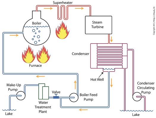
Last time we learned how the condenser within a power plant acts as a conservationist by transforming steam from the turbine exhaust back into water. This previously purified water, or condensate, contains valuable residual heat energy from its earlier journey through the power plant, making it perfect for reuse within the boiler, resulting in both water and fuel savings for the plant. Today we’ll take a look at a highly pressurized form of condensate known as boiler feed water and how it helps the power plant save money by recycling residual heat energy in the steam and water cycle. Let’s begin by integrating the condenser into the big picture, the complete water-to-steam power plant cycle, to see how it fits in. The illustration shows that both the make-up pump and the condenser circulating water pump draw water from the same supply source, in this case a lake. The circulating water pump continuously draws in water to keep the condenser tubes cool, while the make-up pump draws in water only when necessary, such as when initially filling the boiler or to make up for leaks during operation, leaks which typically occur due to worn operating parts. In a nutshell, the condenser recycles steam from the turbine exhaust for its reuse within the power plant. The journey begins when condensate drains from the hot well located at the bottom of the condenser, then gets siphoned into the boiler feed pump. If you recall from a previous article, the boiler feed pump is a powerful pump that delivers water to the boiler at high pressures, typically more than 1,500 pounds per square inch in modern power plants. After its pressure has been raised by the pump, the condensate is known as boiler feed water. The boiler feed water leaves the boiler feed pump and enters the boiler, where it will once again be transformed into steam, and the water-to-steam cycle starts all over again. That is, boiler feed water is turned to steam, it’s superheated to drive the turbine, then condenses back into condensate, and finally it’s returned to the boiler again by the boiler feed pump. Trace its journey along this closed loop by following the yellow arrows in the illustration. While you were following the arrows you may have noticed a new valve in the illustration. It’s on the pipe leading from the water treatment plant to the boiler feed pump. Next time we’ll see how this small but important item comes into play in the operation of our basic power plant steam and water cycle. ________________________________________ |
Posts Tagged ‘power generation’
Boiler Feed Water, A Special Kind of Condensate
Tuesday, October 22nd, 2013Superheating, Part 2
Sunday, August 25th, 2013|
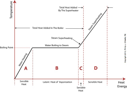
Last time we added a piece of equipment called a superheater, positioned between the boiler and steam turbine, to our basic electric utility power plant steam and water cycle. Its addition enables a greater and more consistent supply of heat energy to the steam which powers the turbine. How much more? Let’s look at Figure 1 to get an idea. Figure 1
You may have noticed that our illustration lacks numerical representation. That’s because power plants are designed differently, depending on fuels used and power output required. So unless we’re talking about a particular power plant, number values would be impractical. For example, I could specify a boiling point of 596°F at 1,500 pounds per square inch (PSI), and a superheater outlet temperature of 1,050°F at 1,200PSI, and I could make note of esoteric things like enthalpy (British Thermal Units per pound mass) values on the Heat Energy axis. But to facilitate our discussion we’ll keep things simple and focus on the general process. Figure 1 shows in phase D the additional heat energy being added to the steam, thanks to the superheater. This is significantly more than had been added by the boiler alone, as represented by phase C. The turbine consumes heat energy added in phases C and D and converts it into mechanical energy to drive the generator, resulting in electrical energy being provided to consumers in the most energy efficient way possible. But increasing power output and efficiency isn’t the superheater’s only job. The heat it adds during phase D ensures the turbine’s safe operation when it’s cranking at full capacity, as represented by the superheated steam zones of phases C and D. Next week we’ll discover how the superheater prevents a destructive process known as condensing from occurring inside the turbine. ________________________________________ |
Coal Power Plant Fundamentals – The Generator
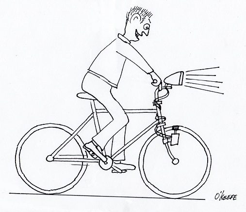
Monday, March 7th, 2011| When I was a kid I remember how cool it was to have a headlight on my bike. Unlike the headlights that the other kids had, mine was not powered with flashlight batteries. The power came from a little gadget with a small wheel that rode on the front tire. As I pedaled along, the tire’s spinning caused the small wheel to spin, and voila, the headlight bulb came to life. Little did I know that this gadget was a simple form of electrical generator, and of course I was oblivious to the fact that a similar device, albeit on a much larger scale, was being used at a nearby power plant to send electricity to my home.
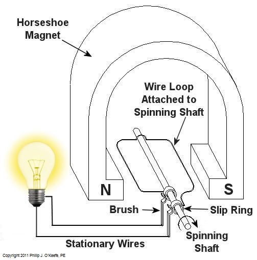
Over the last few weeks we learned how a coal fired power plant transforms chemical energy stored in coal into heat energy and then into mechanical energy which enables a steam turbine shaft to spin. We’ll now turn our attention to the electrical generator. It’s responsible for performing the last step in the energy conversion process, that is, it converts mechanical energy from the steam turbine into the desired end product, electrical energy for our use. It represents the culmination in energy’s journey through the power plant, the process by which energy contained in a lump of coal is transformed into electricity. To show how this final energy conversion process works, let’s look at Figure 1, a simplified illustration of an electrical generator. Figure 1 – A Basic Electrical Generator You’ll note that the generator in our illustration has a shaft with a loop of wire attached to it. When the shaft spins, so does the loop. The shaft and wire loop are placed between the north (N) and south (S) poles of a horseshoe magnet. It’s a permanent magnet, so it always has invisible lines of magnetic flux traveling between its two poles. These magnetic lines of flux are the same type as the ones created by kids’ magnets, when they play with watching paperclips jump up to meet the magnet. The properties of magnets are not completely understood, even to adults who work with them every day. And what could be more mysterious than the fact that as the shaft and wire loop spin through the lines of magnetic flux in the generator, an electric current is produced in the wire loop. Now, this current that’s flowing through the spinning wire loop is of no use if we can’t channel it out of the generator. The wire loop is spinning vigorously, so you can’t directly connect the ends of the loop to stationary wires. A special treatment is required. Each end of the loop is connected to a slip ring. A part called a “brush” presses against each slip ring to make electrical contact. The electrical current then flows from the loop through the spinning slip rings, through the brushes, and into the stationary wires. So, if, for example, a light bulb is connected to the other end of the stationary wires, this completes an electric circuit through which current can flow. The light bulb will glow as long as the generator shaft keeps spinning and the wire loop keeps passing through the magnetic lines of flux from the magnet. So we see that the key to the whole energy conversion process is to have movement between magnetic lines of flux and a loop of wire. As long as this movement occurs, the electricity will flow. This basic principle is the same in a coal fired power plant, but the electrical generator is far more complicated in construction and operation than shown here. My Coal Power Plant Fundamentals seminar goes into far greater detail on this and other aspects of electricity generation, but what I have shared with you above will give you a basic understanding of how they operate. That concludes our journal with coal through the power plant. This series of blogs has, you will remember, presented a simplified version of the complex material presented in my teaching seminars. Next week we’ll branch off, taking a look at why electrical wires come in different thicknesses. _____________________________________________
|


