Archive for September, 2016

Mechanical Advantage of a Compound Pulley

Thursday, September 29th, 2016

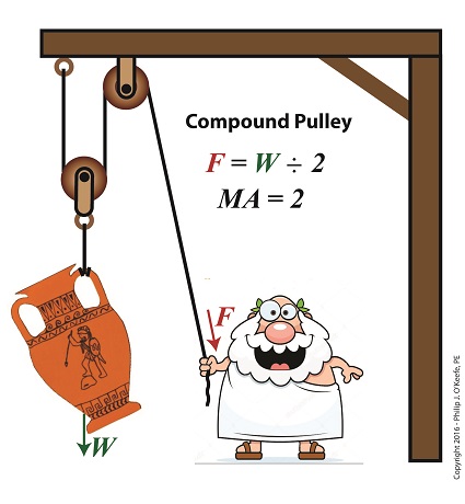
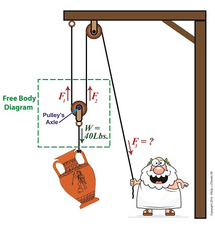
    In this blog series on pulleys we’ve gone from discussing the simple pulley to the improved simple pulley to an introduction to the complex world of compound pulleys, where we began with a static representation.   We’ve used the engineering tool of a free body diagram to help us understand things along the way, and today we’ll introduce another tool to prepare us for our later analysis of dynamic compound pulleys.   The tool we’re introducing today is the engineering concept of mechanical advantage, MA, as it applies to a compound pulley scenario.

    The term mechanical advantage is used to describe the measure of force amplification achieved when humans use tools such as crowbars, pliers and the like to make the work of prying, lifting, pulling, bending, and cutting things easier.   Let’s see how it comes into play in our lifting scenario.

    During our previous analysis of the simple pulley, we discovered that in order to keep the urn suspended, Mr. Toga had to employ personal effort, or force, equal to the entire weight of the urn.

F = W                                    (1)

    By comparison, our earlier discussion on the static compound pulley revealed that our Grecian friend need only exert an amount of personal force equal to 1/2 the suspended urn’s weight to keep it in its mid-air position.   The use of a compound pulley had effectively improved his ability to suspend the urn by a factor of 2.   Mathematically, this relationship is demonstrated by,

F = W ÷ 2                              (2)

    The factor of 2 in equation (2) represents the mechanical advantage Mr. Toga realizes by making use of a compound pulley.   It’s the ratio of the urn’s weight force, W, to the employed force, F.   This is represented mathematically as,

MA = W ÷                           (3)

    Substituting equation (2) into equation (3) we arrive at the mechanical advantage he enjoys by making use of a compound pulley,

MA = W ÷ (W ÷ 2) = 2           (4)

Mechanical Advantage of a Compound Pulley

Mechanical Advantage of  a Compound Pulley

    Next time we’ll apply what we’ve learned about mechanical advantage to a compound pulley used in a dynamic lifting scenario.


 Copyright 2016 – Philip J. O’Keefe, PE

Engineering Expert Witness Blog

____________________________________


Archimedes and the Compound Pulley

Thursday, September 22nd, 2016

    Archimedes, a Greek mathematician of ancient times, is credited with inventing the compound pulley, a subject we’ve been exploring recently.  He was so confident in his invention, he’s said to have remarked, “I could move the Earth if given the right place to stand.”

Archimedes and the Compound Pulley

Archimedes and the Compound Pulley

 Copyright 2016 – Philip J. O’Keefe, PE

Engineering Expert Witness Blog

____________________________________


The Math Behind a Static Compound Pulley

Friday, September 9th, 2016

    Last time we introduced the compound pulley and saw how it improved upon a simple pulley, both of which I’ve engaged in my work as an engineering expert.  Today we’ll examine the math behind the compound pulley.   We’ll begin with a static representation and follow up with an active one in our next blog.

    The compound pulley illustrated below contains three rope sections with three representative tension forces, F1, F2, and F3.   Together, these three forces work to offset the weight, W, of a suspended urn weighing 40 lbs.   Weight itself is a downward pulling force due to the effects of gravity.

    To determine how our pulley scenario affects the man holding his section of rope and exerting force F3, we must first calculate the tension forces F1 and F2.   To do so, we’ll use a free body diagram, shown in the green box, to display the forces’ relationship to one another.

A Compound Pulley

The Math Behind a Static Compound Pulley

    The free body diagram only takes into consideration the forces inside the green box, namely F1, F2, and W.

    For the urn to remain suspended stationary in space, we know that F1 and F2 are each equal to one half the urn’s weight, because they’re spaced equidistant from the pulley’s axle, which directly supports the weight of the urn.  Mathematically this looks like,

F1 = F2 = W ÷ 2

    Because we know F1 and F2, we also know the value of F3, thanks to an engineering rule concerning pulleys.  That is, when a single rope is used to support an object with pulleys, the tension force in each section of rope must be equal along the entire length of the rope, which means F1 = F2 = F3.    This rule holds true whether the rope is threaded through one simple pulley or a complex array of fixed and moveable simple pulleys within a compound pulley.   If it wasn’t true, then unequal tension along the rope sections would result in some sections being taut and others limp, which would result in a situation which would not make lifting the urn any easier and thereby defeat the purpose of using pulleys.

    If the urn’s weight, W, is 40 pounds, then according to the aforementioned engineering rule,

F1 = F2 = F3= W ÷ 2

F1 = F2 = F3 =  (40 pounds) ÷ 2 = 20 pounds

    Mr. Toga needs to exert a mere 20 pounds of personal effort to keep the immobile urn suspended above the ground.   It’s the same effort he exerted when using the improved simple pulley in a previous blog, but this time he can do it from the comfort and safety of standing on the ground.

    Next time we’ll examine the math and mechanics behind an active compound pulley and see how movement affects F1 , F2 , and F3.


Copyright 2016 – Philip J. O’Keefe, PE

Engineering Expert Witness Blog

____________________________________