Posts Tagged ‘weight force’

Friction Reduces Pulleys’ Mechanical Advantage

Tuesday, December 13th, 2016

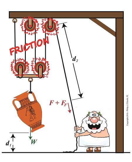
   The presence of friction in mechanical designs is as guaranteed as conflict in a good movie, and engineers inevitably must deal with the conflicts friction produces within their mechanical designs.   But unlike a good movie, where conflict presents a positive, engaging force, friction’s presence in pulleys results only in impediment, wasting energy and reducing mechanical advantage.  We’ll investigate the math behind this phenomenon in today’s blog.

Friction Reduces Pulleys’ Mechanical Advantage

Friction Reduces Pulleys’ Mechanical Advantage


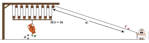
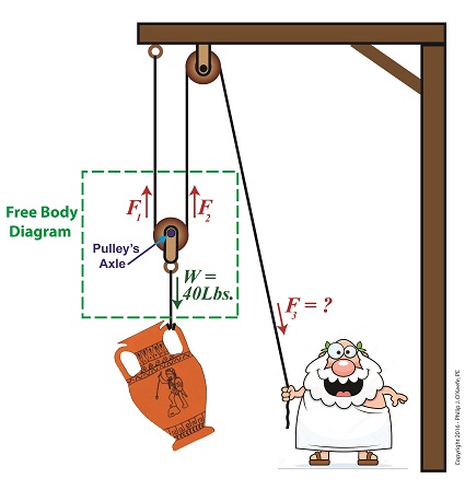
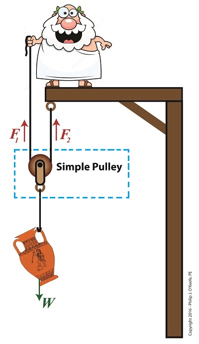
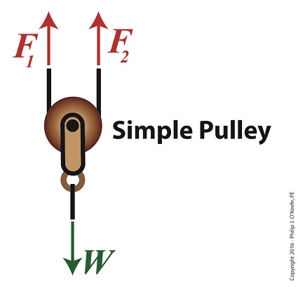
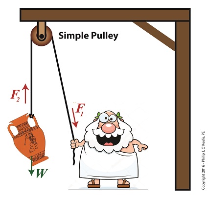
   A few blogs back we performed a work input-output analysis of an idealized situation in which no friction is present in a compound pulley.   The analysis yielded this equation for mechanical advantage,

                                                MA = d2 ÷ d1                       (1)

where d2 is the is the length of rope Mr. Toga extracts from the pulley in order to lift his urn a distance d1 above the ground.   Engineers refer to this idealized frictionless scenario as an ideal mechanical advantage, IMA, so equation (1) becomes,

                                                IMA = d2 ÷ d1                       (2)

   We also learned that in the idealized situation mechanical advantage is the ratio of the urn’s weight force, W, to the force exerted by Mr. Toga, F, as shown in the following equation.   See our past blog for a refresher on how this ratio is developed.

                                                IMA = W ÷ F                          (3)

   In reality, friction exists between a pulley’s moving parts, namely, its wheels and the rope threaded through them.   In fact, the more pulleys we add, the more friction increases.

   The actual amount of lifting force required to lift an object is a combination of FF , the friction-filled force, and F, the idealized friction-free force.  The result is FActual as shown here,

                                                FActual = F + FF                       (4)

   The real world scenario in which friction is present is known within the engineering profession as actual mechanical advantage, AMA, which is equal to,

                                                AMA = W ÷ FActual                  (5)

   To see how AMA is affected by friction force FF, let’s substitute equation (4) into equation (5),

                                                AMA = W ÷ (F + FF)                (6)

   With the presence of FF in equation (6), W gets divided by the sum of F and FF .   This results in a smaller number than IMA, which was computed in equation (3).   In other words, friction reduces the actual mechanical advantage of the compound pulley.

   Next time we’ll see how the presence of FF translates into lost work effort in the compound pulley, thus creating an inequality between the work input, WI and work output WO.

 Copyright 2016 – Philip J. O’Keefe, PE

Engineering Expert Witness Blog

____________________________________


Rope Length Tradeoff in a Compound Pulley

Friday, November 18th, 2016

    We’re all familiar with the phrase, “too much of a good thing.”  As a professional engineer, I’ve often found this to be true.   No matter the subject involved, there inevitably comes a point when undesirable tradeoffs occur.   We’ll begin our look at this phenomenon in relation to compound pulleys today, and we’ll see how the pulley arrangement we’ve been working with encounters a rope length tradeoff.   Today’s arrangement has a lot of pulleys lifting an urn a short distance.

    We’ll be working with two distance/length factors and observe what happens when the number of pulleys is increased.   Last time we saw how the compound pulley is essentially a work input-output device, which makes use of distance factors.   In our example below, the first distance/length factor, d1, pertains to the distance the urn is lifted above the ground.   The second factor, d2, pertains to the length of rope Mr. Toga extracts from the pulley while actively lifting.   It’s obvious that some tradeoff has occurred just by looking at the two lengths of rope in the image below as compared to last week.   What we’ll see down the road is that this also affects mechanical advantage.

    The compound pulley here consists of 16 pulleys, therefore it provides a mechanical advantage, MA, of 16.   For a refresher on how MA is determined, see our preceding blog.

Rope Length Tradeoff in a Compound Pulley

Rope Length Tradeoff in a Compound Pulley


    With an MA of 16 and the urn’s weight, W, at 40 pounds, we compute the force, F, Mr. Toga must exert to actively lift the urn higher must be greater than,

F > W ÷ MA

F > 40 Lbs. ÷ 16

 F > 2.5 Lbs.

    Although the force required to lift the urn is a small fraction of the urn’s weight, Mr. Toga must work with a long and unwieldy length of rope.   How long?   We’ll find out next time when we’ll take a closer look at the relationship between d1 and d2.

 Copyright 2016 – Philip J. O’Keefe, PE

Engineering Expert Witness Blog

____________________________________


The Math Behind a Static Compound Pulley

Friday, September 9th, 2016

    Last time we introduced the compound pulley and saw how it improved upon a simple pulley, both of which I’ve engaged in my work as an engineering expert.  Today we’ll examine the math behind the compound pulley.   We’ll begin with a static representation and follow up with an active one in our next blog.

    The compound pulley illustrated below contains three rope sections with three representative tension forces, F1, F2, and F3.   Together, these three forces work to offset the weight, W, of a suspended urn weighing 40 lbs.   Weight itself is a downward pulling force due to the effects of gravity.

    To determine how our pulley scenario affects the man holding his section of rope and exerting force F3, we must first calculate the tension forces F1 and F2.   To do so, we’ll use a free body diagram, shown in the green box, to display the forces’ relationship to one another.

A Compound Pulley

The Math Behind a Static Compound Pulley

    The free body diagram only takes into consideration the forces inside the green box, namely F1, F2, and W.

    For the urn to remain suspended stationary in space, we know that F1 and F2 are each equal to one half the urn’s weight, because they’re spaced equidistant from the pulley’s axle, which directly supports the weight of the urn.  Mathematically this looks like,

F1 = F2 = W ÷ 2

    Because we know F1 and F2, we also know the value of F3, thanks to an engineering rule concerning pulleys.  That is, when a single rope is used to support an object with pulleys, the tension force in each section of rope must be equal along the entire length of the rope, which means F1 = F2 = F3.    This rule holds true whether the rope is threaded through one simple pulley or a complex array of fixed and moveable simple pulleys within a compound pulley.   If it wasn’t true, then unequal tension along the rope sections would result in some sections being taut and others limp, which would result in a situation which would not make lifting the urn any easier and thereby defeat the purpose of using pulleys.

    If the urn’s weight, W, is 40 pounds, then according to the aforementioned engineering rule,

F1 = F2 = F3= W ÷ 2

F1 = F2 = F3 =  (40 pounds) ÷ 2 = 20 pounds

    Mr. Toga needs to exert a mere 20 pounds of personal effort to keep the immobile urn suspended above the ground.   It’s the same effort he exerted when using the improved simple pulley in a previous blog, but this time he can do it from the comfort and safety of standing on the ground.

    Next time we’ll examine the math and mechanics behind an active compound pulley and see how movement affects F1 , F2 , and F3.


Copyright 2016 – Philip J. O’Keefe, PE

Engineering Expert Witness Blog

____________________________________


Using a Free Body Diagram to Understand Simple Pulleys

Thursday, July 21st, 2016

    Sometimes the simplest alteration in design results in a huge improvement, a truth I’ve discovered more than a few times during my years as an engineering expert.   Last time we introduced the simple pulley and revealed that its usefulness was limited to the strength of the pulling force behind it.   Hundreds of years ago that force was most often supplied by a man and his biceps.   But ancient Greeks found an ingenious and simple way around this limitation, which we’ll highlight today by way of a modern design engineer’s tool, the free body diagram.

    Around 400 BC, the Greeks noticed that if they detached the simple pulley from the beam it was affixed to in our last blog and instead allowed it to be suspended in space with one of its rope ends fastened to a beam, the other rope end to a pulling force, something interesting happened.

The Simple Pulley Improved

The Simple Pulley Improved

    It was much easier to lift objects while suspended in air.  As a matter of fact, it took 50% less effort.   To understand why, let’s examine what engineers call a free body diagram of the pulley in our application, as shown in the blue inset box and in greater detail below.

Free Body Diagram of an Improved Simple Pulley

Using a Free Body Diagram to Understand Simple Pulleys

    The blue insert box in the first illustration highlights the subject at hand.   A free body diagram helps engineers analyze forces acting upon a stationary object suspended in space.   The forces acting upon the object, in our case a simple pulley, represent both positive and negative values.   The free body diagram above indicates that forces pointing up are, by engineering convention, considered to be positive, while downward forces are negative.   The basic rule of all free body diagrams is that in order for an object to remain suspended in a fixed position in space, the sum of all forces acting upon it must equal zero.

    We’ll see how the free body diagram concept is instrumental in understanding the improvement upon the action of a simple pulley next time, when we attack the math behind it.

Copyright 2016 – Philip J. O’Keefe, PE

Engineering Expert Witness Blog

____________________________________


The Simple Pulley Gives Us a Lift

Friday, July 8th, 2016

    Lifting heavy objects into position always presents a challenge, whether it’s a mom lifting a toddler to her hip or a construction worker lifting work materials to great heights.   During my career as an engineering expert I’ve dealt with similar challenges, some of which were handled quite nicely by incorporating a simple pulley, which we introduced last time, into my design.   But sometimes, due to certain restrictions, the addition of a simple pulley into the works isn’t enough to get the job done.   We’ll take a look at one of the restrictions working against the use of a simple pulley today.

    The simple pulley is believed to have first been used by the Greeks as far back as the 9th Century BC.   Back then it would have come in handy to lift cargo aboard ships, hoist sails on masts, and lift building materials high off the ground to supply workmen during the construction of temples and other marvels of ancient architecture.   In other words, pulleys literally saved ancient workers thousands of steps when it came to lifting things off the ground.

    Let’s return to ancient times for a moment to get an understanding of the mechanics behind the workings of the simple pulley as put to use in a basic lifting application.

 The Simple Pulley Gives Us a Lift

The Simple Pulley Gives Us a Lift


    With a simple pulley, the tension force F1 applied to the rope by the pull-er is equal to the tension force F2 exerted upon the object, the pull-ee.   Once lifted off the ground, these forces are also equal to the object’s weight, W, which gravity works upon to return the lifted object to its previous position on the ground.  All these forces come to bear upon whatever’s doing the pulling.   If this pull-er happens to be a human, then the simple pulley’s effectiveness to lift things is directly proportionate to that human’s strength.   In the case of the toga’d figure above, that would be about 10 pounds.   It’s this caveat that limits the usefulness of the simple pulley when relying on human power alone, particularly when it’s employed to lift extremely heavy objects like marble pillars.   A single human isn’t up to the task.

    Next time we’ll see how ancient Greeks overcame this limitation of the simple pulley by managing to cut in half the amount of brute force required to lift heavy objects.

Copyright 2016 – Philip J. O’Keefe, PE

Engineering Expert Witness Blog

____________________________________


Calculating the Force of Friction

Wednesday, April 27th, 2016

    Last time we introduced the frictional force formula which is used to calculate the force of friction present when two surfaces move against one another, a situation which I as an engineering expert must sometimes negotiate.   Today we’ll plug numbers into that formula to calculate the frictional force present in our example scenario involving broken ceramic bits sliding across a concrete floor.

   Here again is the formula to calculate the force of friction,

FF = μ × m × g

where the frictional force is denoted as FF, the mass of a piece of ceramic sliding across the floor is m, and g is the gravitational acceleration constant, which is present due to Earth’s gravity.   The Greek letter μ, pronounced “mew,” represents the coefficient of friction, a numerical value predetermined by laboratory testing which represents the amount of friction at play between two surfaces making contact, in our case ceramic and concrete.

    To calculate the friction present between these two materials, let’s suppose the mass m of a given ceramic piece is 0.09 kilograms, μ is 0.4, and the gravitational acceleration constant, g, is as always equal to 9.8 meters per second squared.


Calculating the Force of Friction

Calculating the Force of Friction


    Using these numerical values we calculate the force of friction to be,

FF = μ × m × g

FF = (0.4) × (0.09 kilograms) × (9.8 meters/sec2)

FF = 0.35 kilogram meters/sec2

FF = 0.35 Newtons

    The Newton is shortcut notation for kilogram meters per second squared, a metric unit of force.   A frictional force of 0.35 Newtons amounts to 0.08 pounds of force, which is approximately equivalent to the combined stationary weight force of eight US quarters resting on a scale.

    Next time we’ll combine the frictional force formula with the Work-Energy Theorem formula to calculate how much kinetic energy is contained within a single piece of ceramic skidding across a concrete floor before it’s brought to a stop by friction.

Copyright 2016 – Philip J. O’Keefe, PE

Engineering Expert Witness Blog

____________________________________