|
Last week we looked at how a mechanical brake stopped a rotating wheel by converting its mechanical energy, namely kinetic energy, into heat energy. This week, we’ll see how a dynamic brake works. Chances are you have directly benefited by a dynamic braking system the last time you rode in an elevator. But, to understand the basic principle behind an elevator’s dynamic brake system, let’s first take a look at the electric braking system in Figure 1 below.
Figure 1 – A Simple Electric Braking System Here the brake consists of an electric generator wired via an open switch to an electrical component called a resistor. The weight is attached to a cable that is wound around a pulley on the generator’s shaft. As the weight freefalls, the cable unwinds on the pulley, causing the pulley to turn the generator’s shaft. Unlike last week’s mechanical brake which required a good deal of effort to employ, a dynamic braking system requires very little. All that needs to be done is to close a switch as shown in Figure 2 below. When the switch is closed, an electrical circuit is created where the resistor gets connected to the generator. The resistor does as its name implies: it resists (but doesn’t stop) the electrical current flowing through it from the generator. As the electrical current fights its way through the resistor to get back to the generator, the resistor gets hot like an electric heater. This heat is dissipated to the cooler surrounding air. At the same time, the weight begins to slow down in its descent. But how is this happening? The electric braking system can be thought of as an energy conversion process. We start out with the kinetic, or motion energy, of the freefalling weight. This kinetic energy is transmitted to the electrical generator by the cable, which spins the generator’s shaft as the cable unwinds. Electrical generators are machines that convert kinetic energy into electrical energy. This energy travels from the electric generator through wires and a closed switch to the resistor. In the process the resistor converts the electrical energy into heat energy. So, kinetic energy is drawn from the falling weight through the conversion process and leaves the process in the form of heat. As the falling weight is drained of kinetic energy, it slows down.
Figure 2 – Applying the Electric Brake Okay, now let’s get back to dynamic brakes on elevators. An elevator is attached by a cable to a hoist that is powered by an electric motor. When it’s time to stop at the desired floor, the automatic control system disconnects the elevator’s electric motor from its power source and turns the motor into a generator. The generator is then automatically connected to a resistor like the one shown in the electric brake above. The kinetic energy of the moving elevator is converted by the generator into electrical energy. The resistor converts the electrical energy into heat energy which is then dissipated into the surrounding environment. The elevator slows down in the process because it’s being robbed of kinetic energy. When the dynamic brake slows the elevator down enough, a mechanical brake is introduced, taking over to bring the elevator to a complete stop. This two-fold process serves to reduce wear and tear on the mechanical brake’s parts, lengthening the operational lifespan of the system as a whole. Next time, we’ll tie everything together and show how mechanical and dynamic brakes work together in a diesel locomotive. _____________________________________________
|
Archive for May, 2010
Dynamic Brakes
Monday, May 31st, 2010


Brakes and Braking Systems
Sunday, May 23rd, 2010|
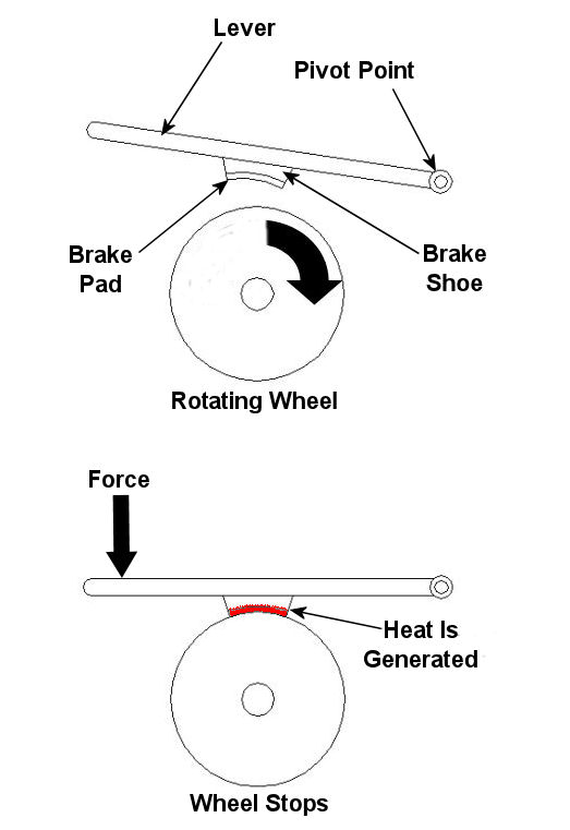
Imagine driving in your car, you’re traveling at a speed of 65 mph and you’re coming up on a curve. You depress your brake pedal to negotiate the turn, and nothing happens… Scenarios just like this one have been in the news quite often lately, brakes which just aren’t operating correctly. We’ve heard the tales of terror, recounted by those unfortunate individuals who have been placed in this situation, but have we reflected on just why their brakes might have failed? Put most simply, a brake is a device whose purpose is to stop a body in motion. This important task is accomplished by converting the kinetic energy (energy of motion) into heat energy. This can be accomplished by either of two methods, mechanically or electrically. In today’s blog we’ll focus on the mechanical aspect. A simple mechanical brake is shown in Figure 1 below. In this arrangement kinetic energy is converted into heat energy when force is applied to a lever, causing a brake shoe to meet up with a rotating wheel. The brake shoe has a pad attached to its surface that makes direct contact with the wheel, and when the two come together great friction is produced. It’s this friction that will ultimately stop the object in motion. Friction turns the kinetic energy into heat energy.
Figure 1 – A Simple Mechanical Brake Friction at its simplest is a mechanical resistance to movement. Whenever two materials in motion come into contact with each other there is always some degree of friction. The extent to which friction is produced by their meeting is referred to as the “coefficient of friction.” The coefficient of friction varies according to the surface character of the materials coming in contact. For example, the coefficient of friction for the leather sole of your shoe on smooth ice is very low. This means you’ll do a lot of slipping when you’re trying to walk, and that’s because ice presents little friction to resist a smoothly soled shoe. But take this same shoe and apply it to the rough surface of concrete, and you’ll be walking quickly and efficiently. Coefficients of friction between different materials have been duly measured in laboratories and are tabulated for easy access in engineering reference books. Based on our simple example above, one would easily come to the conclusion that a high coefficient of friction is desirable when talking about brake shoes, specifically the one represented in Figure 1 above. The higher the coefficient of friction, the more the pad wants to grab the wheel, and the less force you will need to apply to the brake shoe to successfully come to a stop. That’s mechanical braking in a nutshell. Next time, we’ll focus on an electrical braking system known as a “dynamic brake.” _____________________________________________
|


Centrifugal Pumps
Sunday, May 16th, 2010|
Last week we focused on various types of positive displacement pumps. Today we’ll take a look at centrifugal pumps. See Figure 1.
Figure 1 – A Centrifugal Pump Just like the positive displacement pumps we talked about last week, centrifugal pumps have rotating parts as well, but that’s where their similarities end. Unlike positive displacement pumps that take “bites” out of liquid before trapping it between moving parts, centrifugal pumps rely on kinetic energy to move liquid in a continuous stream. Kinetic energy is the energy of motion, and in the case of the centrifugal pump kinetic energy is developed by rotating parts within the pump and transferred to the liquid contained within the pump. In other words, the liquid is moved through the pump by means of centrifugal force. To illustrate this concept, we can tie a rope to the handle of a bucket that has a small hole punched in the bottom. Now, you know what will happen if you fill the bucket with water… There’s a hole in the bucket, Dear Liza, Dear Liza… That’s right, the water will just dribble out of the hole, thanks to gravity. But before we fix the hole as Liza suggests, let’s do an experiment. Pick up the rope and spin the bucket around as fast as you can in a circle. You’ll notice that this rapid spinning creates centrifugal force, resulting in a rather powerful stream of water shooting from the hole. The faster you spin the bucket, the stronger the stream. When it comes to centrifugal pumps, the idea is basically the same. The objective is to forcefully spin water around in a circle, thus ejecting it from the pump. This is accomplished with a rotating part called an impeller. See Figure 2.
Figure 2 – Cutaway View of a Centrifugal Pump
In our illustration the impeller is attached to a shaft that’s powered by some source of mechanical energy, such as an electric motor. The water enters the pump at the center of the rotating impeller, referred to as the “eye.” The water then slides over the face of the impeller, moving from the center to its edge due to the action of centrifugal force. That force pushes it off the impeller and into the pump housing. You’ll note that the housing has a special shape, called a “volute.” This volute looks a lot like a spiraled snail shell. The shape of the volute helps direct the water coming off the impeller into an opening in the side of the pump where it is discharged. The faster the pump impeller rotates, the more kinetic energy the water picks up from the impeller. This ends our discussion on pumps. Next time, we’ll move on to a new topic of discussion, braking systems. _____________________________________________ |


A Pump By Any Other Name…
Monday, May 10th, 2010|
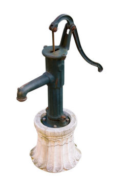
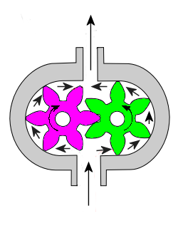
Pumps are all around us. They keep our drinking water flowing, the cooling water circulating in your car’s engine, and even your blood flowing. They’re essential in many aspects of our lives, but most of us don’t think too much about them. For our discussion let’s put them into two categories: positive displacement pumps and centrifugal pumps. This week, we’ll focus on positive displacement pumps. Positive displacement pumps, as their name implies, displace a quantity of liquid with each complete cycle of movement. This takes place when moving parts of the pump take “bites” out of the liquid at the inlet, then force them to exit through the outlet. A familiar example of a positive displacement pump is the type of hand operated water pump that’s commonly found in campgrounds. See Figure 1. Figure 1 – A Positive Displacement Pump This type of pump is known as a reciprocating positive displacement pump. By reciprocating, I mean that the moving parts travel back and forth in a straight line during its operation. Let’s see how it works by referring to the cutaway view in Figure 2. Figure 2 – Cutaway View of the Pump Shown in Figure 1 In the cutaway view, the pump’s piston and internal check valve are shown, and there’s another check valve in the bottom of the pump housing. When you pull up on the handle, the piston moves down into the water in the pump housing, and the pressure caused by this movement forces the check valve in the bottom to slam closed, while the check valve above is forced open. This causes water movement to flood through the open check valve and fill up the space above the piston. When you push down on the handle, the opposite happens. The piston is made to move upward. The upward acceleration of the water above the piston causes the check valve on the piston to slam shut, and this traps the water above it. As the piston moves back up, a suction is created below, which causes the check valve in the bottom of the housing to pop open and more water is drawn up into the space below the piston. Eventually, when the piston gets high enough, the water trapped on top of it will flow out of the spigot. Another type of positive displacement pump is represented by a rotary pump. These pumps operate in a circular motion to move a volume of liquid with each revolution of the pump shaft. This is done by trapping liquid between moving parts, such as gears, lobes, vanes, or screws, and the stationary pump housing itself. To show how this works, refer to the gear pump shown in Figure 3. Its gear teeth mesh together in the middle of the pump, blocking the flow from going straight through and trapping it within the spaces formed by rotating gear teeth and the pump housing. It’s like the water is being forced through a turnstile.
Figure 3 – A Cutaway View of a Gear Pump Next week, we’ll talk about centrifugal pumps and how they move liquids along using centrifugal force.
_____________________________________________
|


Alternative Energy Sprawl
Sunday, May 2nd, 2010|
The last few weeks we’ve been discussing some of the technical and environmental drawbacks of alternative sources of electrical energy and nuclear power generation. This week we’ll take a look at another drawback, that of energy sprawl.
So what exactly is “energy sprawl?” It’s an easily understand concept, but one that is often overlooked by proponents of the alternative energy movement. Energy sprawl is simply the amount of land which is taken over by alternative power sources in order to generate a given amount of electricity, and that number is dauntingly large.
For example, let’s revisit the subject of wind turbines. According to the National Renewable Energy Laboratory (NREL) of the U.S. Department of Energy, each turbine is to be spaced five to ten turbine diameters apart in a wind farm, depending on local conditions. Now the blades of a 2 megawatt (2 million watt) wind turbine are about 260 feet in diameter, and for our example we’ll space them at the prescribed minimum distance of five diameters. The math for this one is easy, 260 times five, which equates to spacing of 1333 feet, or just over a quarter of a mile. That’s right, if you build a wind turbine farm with a whole bunch of these 2 megawatt turbines, they’ll have to be spaced a minimum of a quarter mile apart. You’ll need a lot of acreage.
So based on the calculations above, we’d have to build a wind farm where each 2 megawatt turbine is surrounded by a circle of empty land 1333 feet in radius. We know from geometry that the area of a circle can be calculated by multiplying pi, that is 3.1416, times its radius squared, and this translates into a minimum area of about 5.6 million square feet per 2 megawatts of power generated, or about 2.8 million square feet per megawatt. Just to put this into perspective, a football field has an area of 57,564 square feet. So what we’re actually talking about here is a little more than 48 football fields worth of land per megawatt of electricity generated!
Let’s turn our attention now to solar power generation. We want to generate electricity with their photo-voltaic (PV) panels, and these panels are made of special materials that convert the sun’s energy directly into electricity. Great concept, but here again we’re talking a lot of land. According to the NREL, it’s estimated that 6.4 acres are required to generate 1 megawatt of electricity using PV panels. Since one acre equals 43,560 square feet, we’d need a total of 278,784 square feet of land area per megawatt. After we’ve done the math we discover that this equates to almost five football fields of area per megawatt of electricity generated.
We’ve now established that loads of land space is required to operate multiple options for alternative energy, and you’re probably wondering how this all compares to land usage for fossil fuel (i.e. coal, oil, natural gas) and nuclear power generation. Well, a typical 1000 megawatt coal fired power plant occupies about 148 million square feet. This translates to around 148,000 square feet per megawatt, which is just over two and a half football fields per megawatt. As for a 1000 megawatt nuclear power plant, we’re talking about 28 million square feet that’s typically occupied by an operating plant, and that translates to almost 28,000 square feet per megawatt, or a little less than half of a football field per megawatt.
Math established, it’s a hands down victory for fossil fuel and nuclear plants compared to wind turbine and solar energies when it comes to land usage. Last time I checked tillable land acreage was going down, not up, around cities where electricity demand is highest. Do we start pushing farther outward to build wind turbine and PV farms on vast expanses of land currently occupied by forests or used to grow our food? Which would you rather do, eat or have electricity?
_____________________________________________
|


