Posts Tagged ‘impeller’

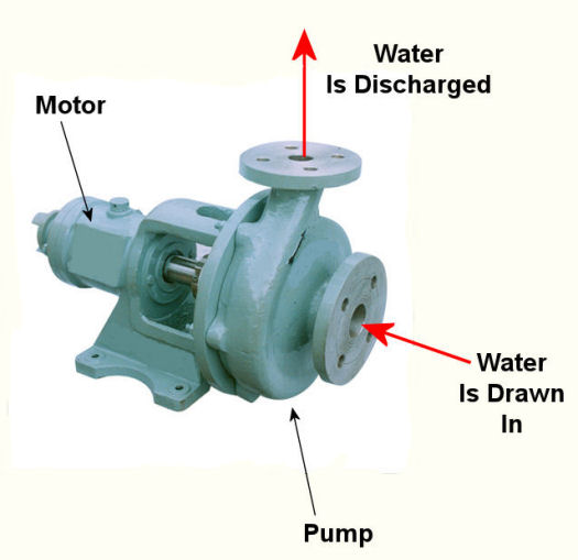
Centrifugal Pump Impeller Action

Friday, March 2nd, 2018

    Last time we discussed how the curved features of a centrifugal pump are key to its functionality.   Today we’ll examine a centrifugal pump’s impeller action and see how it creates a volatile environment inside the pump in which cavitation bubbles flourish.

 Centrifugal Pump Impeller Action

Centrifugal Pump Impeller Action


    Inside a centrifugal pump both low and high pressure areas are created, chiefly due to the action of the pump’s spinning impeller.   Low pressure is created at the water inlet in a way very similar to what happens when you pull the plug on your bathtub.   With the plug removed the drain opens and a tiny whirlpool forms, causing water to get sucked into the plumbing for discharge.

    The same thing happens inside a centrifugal pump due to tumultuous internal water movement.   The spinning impeller vigorously moves water from inlet to discharge.   As water is discharged, a void, or vacuum, is created inside the pump, causing water at the inlet to get sucked inside at low pressure, very much like when you suck liquid through a straw.

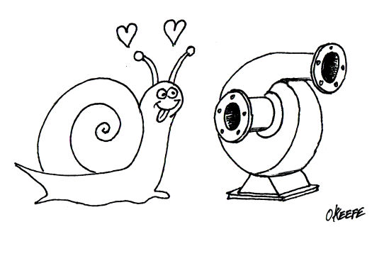
    As water moves inside the housing, it comes into contact with the rotating impeller itself.  This impeller is comprised of multiple spiral curved blades with a volute shape, made to maximize efficient movement of water.   They use the power of centrifugal force to create a high pressure environment, and water is flung at high speed towards the pump’s outlet, where it is then discharged.

    Next time we’ll see how the coexistence of low and high pressures within the centrifugal pump housing create the problem of cavitation bubbles.

opyright 2018 – Philip J. O’Keefe, PE

Engineering Expert Witness Blog

____________________________________


Industrial Ventilation – Local Exhaust Ventilation Fans

Sunday, May 22nd, 2011
    When something is said to be the “heart of the operation,” one usually imagines that it is integral to whatever is being discussed, and it is probably centrally located.  The human heart fits this description well.  This amazing organ, centrally located within your chest cavity, moves blood, nutrients, oxygen, and carbon dioxide through your body with amazing efficiency.   During a twenty four hour period it can pump as much as 2,000 gallons of blood through 6,000 miles of arteries, veins, and capillaries.

     At the heart of a local exhaust ventilation system is its fan.  Like the human heart, it is a model of efficiency.  It first creates a vacuum in the intake hood, which is strategically located at a pollution source, pulling in contaminated air and leading it through ductwork.  Sometimes the fan leads the air to a filter or other air cleaning equipment, but eventually the dirty air is exhausted through a stack leading outdoors.

     There are two main types of fan, axial and centrifugal.  You’re probably most familiar with the axial type, because they’re the type commonly used in tabletop, box, and oscillating fans in your home.  These have blades that look like a propeller on an airplane, and they work by drawing air straight through the fan.  As helpful as they are within a personal setting, axial fans are not typically used in local exhaust ventilation systems because the electric motor that drives the blades is in the path of airflow.  This setup can create a problem if the air flowing over the motor contains dust and flammable vapor.  Dust can cause the motor to get dirty and overheat.  Flammable vapor can ignite if the motor wiring fails and creates an electrical arc.

     Because of the technical difficulties presented by an axial type fan, centrifugal fans are what are most often used in industrial settings.  One such fan is shown in Figure 1.
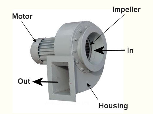
Figure 1 – Centrifugal Fan

     The blades of a centrifugal fan are fully enclosed in air tight housing.  This housing keeps any dust or fumes from leaking out into the building.  The electric motor that drives the fan can be safely located outside of this housing, where it is dust-free and there are no flammable vapors.  If you look inside the housing you will see that the moving part, known as the impeller, resembles a squirrel cage.  See Figure 2.
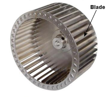
Figure 2 – Centrifugal Fan Impeller

     This impeller is made up of many blades, set up within a wheel configuration.  When an electric motor causes the wheel to rotate, air is made to move off the blades and out of the impeller due to centrifugal force.  This air is sent crashing into the fan housing, shown in Figure 1, which is curved like a spiral to direct the air into an outlet duct which is connected to ductwork that leads to the exhaust stack.  As air leaves the impeller, more air rushes into its center from the inlet duct to occupy the empty space that’s been created.  Hence, as long as the motor keeps spinning the impeller, air will flow through the fan.

     In order for all this to work effectively, the centrifugal fan must be the right size, one that is capable of providing enough suction to capture contaminated air at the hood source, then overcoming the resistance to air flow that is presented by ductwork, filters, and other air cleaning devices. Because air resistance factors such as these impede the fan’s ability to move air through the system, the fan must be of sufficient strength make up for these factors.  To size up the right centrifugal fan for the job, engineers must calculate the resistance to airflow that is expected to be encountered, and to do this they use data supplied by manufacturers of component parts, as well as tabulated data that is readily available in engineering handbooks.  Just as a lawn mower engine won’t provide sufficient energy to power a car, an undersized fan won’t be able to move air through a system which is beyond its capacity limit.

     Next time, we’ll finish our series on local exhaust ventilations systems by looking at the last component in the system:  the exhaust stack.

_____________________________________________
Centrifugal Pumps

Sunday, May 16th, 2010

     Last week we focused on various types of positive displacement pumps.  Today we’ll take a look at centrifugal pumps.  See Figure 1.

Figure 1 – A Centrifugal Pump

     Just like the positive displacement pumps we talked about last week, centrifugal pumps have rotating parts as well, but that’s where their similarities end.  Unlike positive displacement pumps that take “bites” out of liquid before trapping it between moving parts, centrifugal pumps rely on kinetic energy to move liquid in a continuous stream.  Kinetic energy is the energy of motion, and in the case of the centrifugal pump kinetic energy is developed by rotating parts within the pump and transferred to the liquid contained within the pump.  In other words, the liquid is moved through the pump by means of centrifugal force.

     To illustrate this concept, we can tie a rope to the handle of a bucket that has a small hole punched in the bottom.  Now, you know what will happen if you fill the bucket with water…  There’s a hole in the bucket, Dear Liza, Dear Liza…  That’s right, the water will just dribble out of the hole, thanks to gravity.  But before we fix the hole as Liza suggests, let’s do an experiment.  Pick up the rope and spin the bucket around as fast as you can in a circle.  You’ll notice that this rapid spinning creates centrifugal force, resulting in a rather powerful stream of water shooting from the hole.  The faster you spin the bucket, the stronger the stream.

     When it comes to centrifugal pumps, the idea is basically the same.  The objective is to forcefully spin water around in a circle, thus ejecting it from the pump.  This is accomplished with a rotating part called an impeller.  See Figure 2.

Figure 2 – Cutaway View of a Centrifugal Pump    


     In our illustration the impeller is attached to a shaft that’s powered by some source of mechanical energy, such as an electric motor.  The water enters the pump at the center of the rotating impeller, referred to as the “eye.”  The water then slides over the face of the impeller, moving from the center to its edge due to the action of centrifugal force.  That force pushes it off the impeller and into the pump housing.  You’ll note that the housing has a special shape, called a “volute.”  This volute looks a lot like a spiraled snail shell.  The shape of the volute helps direct the water coming off the impeller into an opening in the side of the pump where it is discharged.  The faster the pump impeller rotates, the more kinetic energy the water picks up from the impeller.

     This ends our discussion on pumps.  Next time, we’ll move on to a new topic of discussion, braking systems.

_____________________________________________