Posts Tagged ‘pumps’
Monday, January 15th, 2018
|
Last time we introduced the phenomenon of cavitation, which simply stated is the rapid formation and collapse of vapor bubbles within liquids. It’s a destructive force that eats away at the metal parts of water pumps, used in power plants and other industrial settings. To understand how cavitation comes into play, we’ll explore a branch of engineering known as thermodynamics.
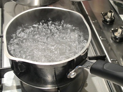
Cavitation doesn’t occur in a glass of water resting on a counter, but bring that water to a boil and the cavitation process will begin. That’s because cavitation is initiated when liquids change form from one physical state to another, in this case from a liquid to a vapor we commonly call steam. All liquids exist in three states, namely solid, liquid, and vapor, but in our thermodynamic analysis we’ll only consider two, liquid and vapor, because cavitation can’t occur in solids.
Thermodynamic Properties of Water and Cavitation
At normal atmospheric pressure of 15 pounds per square inch (PSI) which exists in the average kitchen, water remains in a liquid state between the temperatures of 32ºF and 212ºF. Above 212ºF water begins to boil, transforming into steam vapor. The state in which water exists depends on two thermodynamic properties, namely temperature and pressure. Change one of these variables and it affects the other, and thereby the conditions under which cavitation will occur.
We’ll take an in-depth look at this next time when we revisit the topics of pressurization and vacuums.
opyright 2018 – Philip J. O’Keefe, PE
Engineering Expert Witness Blog
____________________________________ |
Tags: cavitation, engineering, power plants, pumps, states of water, thermodynamics
Posted in Engineering and Science, Expert Witness, Forensic Engineering, Innovation and Intellectual Property, Personal Injury, power plant training, Product Liability | Comments Off on Thermodynamic Properties of Water and Cavitation
Tuesday, June 28th, 2016
|
Pulleys are simple devices with many uses, and as an engineering expert, I’ve often incorporated them into mechanical designs. They’re used in machinery to transmit mechanical power from electric motors and engines to devices like blowers and pumps. Another common usage for pulleys is to aid in lifting. There are two types of pulleys for this purpose, simple or compound. We’ll start our discussion off by looking at the simple type today.
The simple pulley may have been an advanced application of the wheel. It consists of a furrowed wheel on a shaft with some device for pulling threaded through it. The pulley wheel supports and guides the movement of a rope, cable, or other pulling device around its circumference. The pulling device runs between a pull-ee and pull-er, that is, the object to be moved and the source of pulling power, with the pulley itself situated somewhere between them.
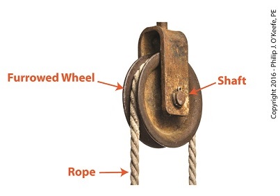
Simple Pulley
Pulleys are believed to have first been used by the Greeks as early as the 9th Century BC. We’ll look into how they put them to use next time.
Copyright 2016 – Philip J. O’Keefe, PE
Engineering Expert Witness Blog
____________________________________ |
Tags: belt, blower, cable, compound pulley, electric motors, engineering expert, engines, mechanical design, pulley, pumps, simple pulleys, transmit mechanical power
Posted in Engineering and Science, Expert Witness, Forensic Engineering, Innovation and Intellectual Property, Personal Injury, Product Liability | Comments Off on Simple Pulleys
Monday, October 28th, 2013
|
Last time we learned how the condenser recycles steam from the turbine exhaust by condensing it back into water for its reuse within the power plant steam-water cycle. This water is known as condensate, and after leaving the boiler feed pump at high pressure, it’s known as boiler feed water. Today we’ll introduce a special valve into the system, whose job it is to perform the important function of compensating for lost water. It’s known as the make-up valve.

The illustration shows the flow of steam and water within the cycle. Tracing the path of orange arrows will reveal it as a closed system.
Under ideal operating conditions recycled condensate from the condenser would provide enough water to keep the boiler indefinitely supplied. In reality water and steam leaks are a chronic problem within power plants, even when well maintained. Leaks typically occur due to worn parts on equipment, a condition which is commonly present due to the demanding operating conditions they must endure. First, there is the strain of continuous operation, then there are the high temperatures, typically greater than 1000°F, and high pressures that pipes, valves, pumps, and the boiler itself must endure. We’re talking about pressure higher than 2000 psi, that is, pounds per square inch. As a result, water levels within the boiler must periodically be replenished.
While tracing the arrows through the diagram, you would have come across the new make-up valve under discussion. It’s located on the pipe leading from the power plant’s water treatment system to the boiler feed pump. It’s normally kept closed, except under two circumstances, when the boiler is initially filled at startup, or when water replenishment needs to take place.
Due to water loss and difficult operating conditions, maintenance within the water-to-steam system of a power plant is a never ending task. There are miles of pipe connected to hundreds of pieces of equipment, all of which are distributed through a huge power plant structure. So the reality is that power plants operate with a continuous eye on leakage.
To contend with the leaks, human intervention is often required in the way of a boiler operator. Their job is to manually open the make-up valve to admit a fresh supply of water from the treatment plant to the boiler via the boiler feed pump. Once the system’s water requirements are replenished, the valve is once again closed.
Next time we’ll continue this series by discussing how the condenser enables the steam turbine to run more efficiently by creating a vacuum at the turbine’s exhaust.
________________________________________
|
Tags: boiler, boiler feed pump, closed system, coal-fired power plant, condensate, condenser, electric utility power plant, engineering expert witness, feed water, forensic engineer, high pressure, high temperature, make up valve, pipe, power engineer, power plant, power plant engineering expert witness, power plant maintenance, power plant operation, power plant training, pumps, start up, steam leaks, steam turbine, steam water cycle, turbine exhaust, vacuum, valves, water leaks, water to steam system, water treatment system
Posted in Engineering and Science, Expert Witness, Forensic Engineering, Innovation and Intellectual Property, Personal Injury, power plant training, Product Liability | Comments Off on The Make-up Valve in the Power Plant Steam to Water Cycle
Monday, February 4th, 2013
| If you’ve been following along with our blog discussion on the systems engineering approach to medical device design, you should by now be convinced that instructions are important. In fact, the meticulous instructions produced during the manufacturing, operating, and maintenance phases of the Development stage are also crucial to later stages, that of Production and Utilization. Let’s finish up our discussion on the Development stage by taking a look at its final aspect, Preproduction.
The Preproduction aspect is instrumental to nipping potential problems in the bud before the medical devices go into actual production. In the initial Preproduction stages, systems engineers coordinate with the manufacturing and purchasing departments within the company as well as outside suppliers. The goal is to acquire all parts and equipment necessary to build a limited number of medical devices on the assembly line. Subjects such as preference in molded plastic components, motors, gears, pumps, springs, electronic components, circuit boards, wire, and tubing are discussed and agreed upon. Vendors are assessed with regard to their ability to produce parts when they are needed and that meet design specifications, satisfy quality requirements, and have costs that fall within budgetary constraints.
The assembly of Preproduction devices provides an opportunity for systems engineers to validate manufacturing and quality control instructions and assess the device design with regard to manufacturability, meaning, the extent to which devices can be manufactured with relative ease, at minimal cost, while maintaining maximum reliability. Devices manufactured during this aspect of the Development stage serve as a test. Are instructions clearly written? Do the device parts fit together as they should? Are parts strong enough to withstand the assembly process? Can the devices be assembled as quickly and easily as expected?
If the answer is “no” to any of these questions, then the device design and instructions must be returned to the design engineers and technical writers. Heads come together to rehash things and work out the bugs.
Next time we’ll continue with the Preproduction aspect of the Development stage to see how laboratory and field testing enables systems engineers to shake out any more bugs from the medical device design, operating instructions, and maintenance instructions.
___________________________________________

|
Tags: assembl, circuit boards, design engineers, Development Stage, electronic components, engineering expert witness, field testing, forensic engineer, gears, instructions, laboratory testing, maintenance, manufacturability, medical device, medical device manufacturing, molded plastic components, motors, preproduction device, Production Stage, pumps, quality requirements, reliability, specifications, springs, systems engineering in medical device design, technical writers, tubing, Utilization Stage, wire
Posted in Engineering and Science, Expert Witness, Forensic Engineering, Innovation and Intellectual Property, Personal Injury, Product Liability, Professional Malpractice | Comments Off on Systems Engineering In Medical Device Design – Preproduction, Part I
Sunday, December 4th, 2011
| When I was a child in school I loved field trips. They didn’t happen too often, but when they did they were a welcomed break from the routine of the classroom. Once we went on a tour of a large factory that made telephones. During the tour we walked amongst gargantuan machines, conveyor belts, furnaces, boilers, pumps, and compressors, all energized and working together to transform raw materials into telephones. Sequences of manufacturing and assembly operations, from the simple to the most complex, were carefully orchestrated with no apparent human intervention.
The equipment in the telephone factory was certainly impressive to watch, and our tour guides did a fine job of explaining what was happening, except for one important detail. I realized after we left that no one had explained who or what was actually controlling the machinery. I realized even then that machines can’t think for themselves. They can only do what humans tell them to do.
I didn’t know it at the time, but the telephone factory setup included some interesting examples of industrial control systems. Industrial control systems can be broken down into two basic categories, manual controls and automatic controls. Manual controls work as their name implies, that is, someone must manually press a button or throw a switch to initiate factory operations. This involves continual monitoring of processes, coupled with hands-on activities to keep everything working.
Automatic controls still require human intervention to some extent, such as initiating operations, but once that’s done they move into self-regulation mode until the operations are shut down at the end of production. Employees are thus freed up to spend time doing things which are not automated. Automatic controls are excellent at handling mundane, repetitive tasks that humans tend to get quickly bored with. Boredom leads to a lack of attention, and this may lead to accidents, so utilizing automatic controls often makes for a safer work environment.
Next time we’ll begin our examination of how manual and automatic controls work within the context of an industrial setting. To begin, we’re going to take a virtual field trip back to the telephone factory and look at some basic industrial control examples.
____________________________________________

|
Tags: accidents, automatic control, boilers, button, compressors, controlling machinery, conveyor belt, engineering expert witness, factory, forensic engineer, furnaces, industrial control, machine control, machines, manual control, process monitoring, pumps, switch, telephones
Posted in Engineering and Science, Expert Witness, Forensic Engineering, Innovation and Intellectual Property, Personal Injury, Product Liability, Professional Malpractice | Comments Off on Industrial Control Basics
Sunday, May 16th, 2010
|
Last week we focused on various types of positive displacement pumps. Today we’ll take a look at centrifugal pumps. See Figure 1.

Figure 1 – A Centrifugal Pump
Just like the positive displacement pumps we talked about last week, centrifugal pumps have rotating parts as well, but that’s where their similarities end. Unlike positive displacement pumps that take “bites” out of liquid before trapping it between moving parts, centrifugal pumps rely on kinetic energy to move liquid in a continuous stream. Kinetic energy is the energy of motion, and in the case of the centrifugal pump kinetic energy is developed by rotating parts within the pump and transferred to the liquid contained within the pump. In other words, the liquid is moved through the pump by means of centrifugal force.
To illustrate this concept, we can tie a rope to the handle of a bucket that has a small hole punched in the bottom. Now, you know what will happen if you fill the bucket with water… There’s a hole in the bucket, Dear Liza, Dear Liza… That’s right, the water will just dribble out of the hole, thanks to gravity. But before we fix the hole as Liza suggests, let’s do an experiment. Pick up the rope and spin the bucket around as fast as you can in a circle. You’ll notice that this rapid spinning creates centrifugal force, resulting in a rather powerful stream of water shooting from the hole. The faster you spin the bucket, the stronger the stream.
When it comes to centrifugal pumps, the idea is basically the same. The objective is to forcefully spin water around in a circle, thus ejecting it from the pump. This is accomplished with a rotating part called an impeller. See Figure 2.

Figure 2 – Cutaway View of a Centrifugal Pump
In our illustration the impeller is attached to a shaft that’s powered by some source of mechanical energy, such as an electric motor. The water enters the pump at the center of the rotating impeller, referred to as the “eye.” The water then slides over the face of the impeller, moving from the center to its edge due to the action of centrifugal force. That force pushes it off the impeller and into the pump housing. You’ll note that the housing has a special shape, called a “volute.” This volute looks a lot like a spiraled snail shell. The shape of the volute helps direct the water coming off the impeller into an opening in the side of the pump where it is discharged. The faster the pump impeller rotates, the more kinetic energy the water picks up from the impeller.
This ends our discussion on pumps. Next time, we’ll move on to a new topic of discussion, braking systems.
_____________________________________________

|
Tags: centrifugal force, centrifugal pump, engineering expert witness, forensic engineer, impeller, kinetic energy, pumps, volute
Posted in Engineering and Science | 2 Comments »


