| My journey through engineering school was marked by a cast of colorful characters from around the world. I remember one Russian professor in particular, fond of extolling the virtues of Russian engineering by the statement, “In Soviet Union steel ingots roll in one door, military tanks roll out other door.” During that period of history in his homeland, it was not uncommon for all components down to the smallest screw to be manufactured within the same factory.
That professor taught me all about clutch mechanisms, and whether they’re present in Soviet tanks or grass trimmers they perform the same basic function. Let’s take a look at one now.
Figure 1
Figure l shows my color-enhanced clutch illustration, which makes it easy to identify the different components of a centrifugal clutch. The main part of the clutch is colored green and it’s respectfully referred to as the “boss.” I assume it’s earned the title due to its role in keeping all component parts of the clutch assembly together. The blue portion shows two clutch shoes. The boss fits loosely into notches within the shoes. The curved surfaces on the shoes are composed of a high friction material, and we’ll see why later. Two springs attached to the shoes cause them to pull towards each other and keep them from falling off the ends of the boss. The yellow portion shows the engine shaft coupling. It’s permanently affixed to the center of the boss. This coupling has a hole in it that enables the clutch mechanism to be attached onto an engine shaft with a threaded nut or some other type of mechanical fastener. Now that we’re familiar with a centrifugal clutch’s parts we can see how they come into play in a real world application, that of an engine shaft. We’ll explore that next week. ____________________________________________
|
Posts Tagged ‘factory’
Mechanical Power Transmission – The Centrifugal Clutch Mechanism
Sunday, April 15th, 2012
Industrial Control Basics – Motor Overload
Sunday, March 4th, 2012|
Last summer my wife and I did a lot of work in the garden. Many holes were dug, bags of garden soil lifted, and plants planted. It’s a new garden, and my wife has very big plans for it, so needless to say there was a lot of work to be done. On more than one occasion we would end the day moaning about our body aches and how we had overdone it. The next day we would hurt even worse, and we’d end up taking time off to recuperate. Pain is your body’s way of telling you that it needs attention, and you’d better listen to it or you may have an even heavier price to pay down the road. Electric motors can get overworked, just like our bodies. Motors are often placed into situations where they are expected to perform tasks beyond their capability. Sometimes this happens through poor planning, sometimes due to wishful thinking on the user’s part. Motors can sustain damage when stressed in this way, but they don’t have a pain system to tell them to stop. Instead, motors benefit by a specific type of electric relay known as an overload relay. But before we get into how an overload relay works, let’s get a better understanding of how overloads happen. Suppose we’re back in the telephone factory discussed in previous blogs, watching a conveyor belt move phones through the manufacturing process. An electric motor drives the conveyor belt by converting electrical energy into mechanical energy. Everything is moving along normally when all of a sudden a machine malfunctions. Telephones start piling up on a belt, and the pile up gets so bad the belt eventually gets jammed and its motor overloaded. If the electricity flow to the motor isn’t shut down promptly by means of a nearby emergency stop button or an astute operator sitting in central control, then an even bigger problem is in the making, that of a potential fire. When electricity is applied to motors they begin to operate, and their natural tendency is to want to keep operating. They do so by continuously drawing energy from the electric current being supplied to them. The greater the workload demand on the motor, the more current it requires to operate. When motors become overloaded as in the scenario presented above, they continue to draw energy unless forced to a stop. The result is an overabundance of current flowing through the motor and no outlet for its task of converting electrical energy into mechanical energy. And where is all that pent up energy to go? It becomes heat energy trapped inside the motor itself, and this heat can build up to the point where the motor becomes damaged or even bursts into flames. Next time we’ll look at how overload relays work to keep electric motors from overheating, just as our body’s pain sensors protect us from overdoing it.
____________________________________________
|

Industrial Control Basics – Electric Motor Control
Sunday, February 19th, 2012| Electric motors are everywhere, from driving the conveyor belts, tools, and machines found in factories, to putting our household appliances in motion. The first electric motors appeared in the 1820s. They were little more than lab experiments and curiosities then, as their useful potential had not yet been discovered. The first commercially successful electric motors didn’t appear until the early 1870s, and they could be found driving industrial devices such as pumps, blowers, and conveyor belts.
In our last blog we learned how a latched electric relay was unlatched at the push of a button, using red and green light bulbs to illustrate the control circuit. Now let’s see in Figure 1 how that circuit can be modified to include the control of an electric motor that drives, say, a conveyor belt inside a factory.
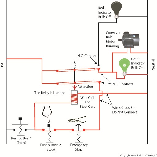
Figure 1
Again, red lines in the diagram indicate parts of the circuit where electrical current is flowing. The relay is in its normal state, as discussed in a previous article, so the N.O. contacts are open and the N.C. contact is closed. No electric current can flow through the conveyor motor in this state, so it isn’t operating. Our green indicator bulb also does not operate because it is part of this circuit. However current does flow through the red indicator bulb via the closed N.C. contact, causing the red bulb to light. The red and green bulbs are particularly useful as indicators of the action taking place in the electric relay circuit. They’re located in the conveyor control panel along with Buttons 1 and 2, and together they keep the conveyor belt operator informed as to what’s taking place on the line, such as, is the belt running or stopped? When the red bulb is lit the operator can tell at a glance that the conveyor is stopped. When the green bulb is lit the conveyor is running. So why not just take a look at the belt itself to see what’s happening? Sometimes that just isn’t possible. Control panels are often located in central control rooms within large factories, which makes it more efficient for operators to monitor and control all operating equipment from one place. When this is the case, the bulbs act as beacons of the activity taking place on the line. Now, let’s go to Figure 2 to see what happens when Button 1 is pushed.
Figure 2
The relay’s wire coil becomes energized, causing the relay armatures to move. The N.C. contact opens and the N.O. contacts close, making the red indicator bulb go dark, the green indicator bulb to light, and the conveyor belt motor to start. With these conditions in place the conveyor belt starts up. Now, let’s look at Figure 3 to see what happens when we release Button 1.
Figure 3
With Button 1 released the relay is said to be “latched” because current will continue to flow through the wire coil via one of the closed N.O. contacts. In this condition the red bulb remains unlit, the green bulb lit, and the conveyor motor continues to run without further human interaction. Now, let’s go to Figure 4 to see how we can stop the motor.
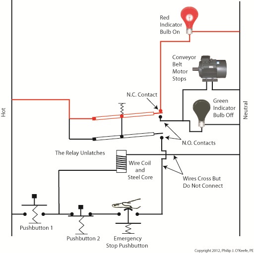
Figure 4
When Button 2 is depressed current flow through the relay coil interrupted. The relay is said to be unlatched and it returns to its normal state where both N.O. contacts are open. With these conditions in place the conveyor motor stops, and the green indicator bulb goes dark, while the N.C. contact closes and the red indicator bulb lights. Since the relay is unlatched and current no longer flows through its wire coil, the motor remains stopped even after releasing Button 2. At this point we have a return to the conditions first presented in Figure 1. The ladder diagram shown in Figure 5 represents this circuit.
Figure 5
Next time we’ll introduce safety elements to our circuit by introducing emergency buttons and motor overload switches. ____________________________________________ |


Industrial Control Basics – Manual Control
Monday, December 12th, 2011| You’ve probably heard the saying, “asleep at the switch.” It’s usually associated with some sort of disaster, found later to have been caused by human error. Someone wasn’t paying attention, and something very bad happened. The meltdown of the Soviet nuclear power plant Chernobyl in 1986 comes to mind. You may be surprised to learn that the saying has its origins in the world of industrial controls, or more specifically, manual controls, as we’ll see in this article.
Last week when we opened our discussion on manual controls, we talked about how they work just as their name implies, that is, someone must manually press a button or throw a switch in order to initiate a factory operation. In other words, a manual control requires human intervention to initiate an action, such as pushing the start button. The machine will then continue to run until a person hits the stop button. Let’s go now on a virtual field trip into a telephone factory to see how a basic manual control system works. It has a conveyor belt operated by an electric motor, and this motor is connected by wires and a power switch to a 120 volt power source of alternating current. Figure 1 illustrates what we mean. It shows that when the power switch is in the open position, a physical air gap exists within the electrical circuit. This prevents electricity from flowing through the wire because electricity can’t jump over gaps.
Figure 1 – Open Power Switch Enter a human into the scenario, someone who grabs the power switch handle and manually closes it, eliminating the air gap. See Figure 2.
Figure 2 – Closed Power Switch When the power switch is closed, a metal conductor bridges the gap, causing electricity to flow through the metal conductor to the electric motor in the circuit. This brings life to the conveyor belt. As long as the power switch remains closed, the conveyor belt will continue to operate. That’s it, that’s a basic manual control system. It’s simple to operate, but it does have one major flaw. It requires constant monitoring by a human. Aside from opening and closing a power switch, humans are required to monitor operations, in case something goes wrong. The operator watching over an industrial machine performs the same function as the pilot on a plane, that is, to start-stop operations, and to intervene in case of an emergency. Computers fly modern jets. Pilots serve as trouble shooters when the unanticipated disaster situation occurs, because computers can’t yet creatively problem solve. Next time we’ll introduce the element of an automatic control system, which will virtually eliminate the need for human intervention and with it human error. ____________________________________________ |


Industrial Control Basics
Sunday, December 4th, 2011| When I was a child in school I loved field trips. They didn’t happen too often, but when they did they were a welcomed break from the routine of the classroom. Once we went on a tour of a large factory that made telephones. During the tour we walked amongst gargantuan machines, conveyor belts, furnaces, boilers, pumps, and compressors, all energized and working together to transform raw materials into telephones. Sequences of manufacturing and assembly operations, from the simple to the most complex, were carefully orchestrated with no apparent human intervention.
The equipment in the telephone factory was certainly impressive to watch, and our tour guides did a fine job of explaining what was happening, except for one important detail. I realized after we left that no one had explained who or what was actually controlling the machinery. I realized even then that machines can’t think for themselves. They can only do what humans tell them to do. I didn’t know it at the time, but the telephone factory setup included some interesting examples of industrial control systems. Industrial control systems can be broken down into two basic categories, manual controls and automatic controls. Manual controls work as their name implies, that is, someone must manually press a button or throw a switch to initiate factory operations. This involves continual monitoring of processes, coupled with hands-on activities to keep everything working. Automatic controls still require human intervention to some extent, such as initiating operations, but once that’s done they move into self-regulation mode until the operations are shut down at the end of production. Employees are thus freed up to spend time doing things which are not automated. Automatic controls are excellent at handling mundane, repetitive tasks that humans tend to get quickly bored with. Boredom leads to a lack of attention, and this may lead to accidents, so utilizing automatic controls often makes for a safer work environment. Next time we’ll begin our examination of how manual and automatic controls work within the context of an industrial setting. To begin, we’re going to take a virtual field trip back to the telephone factory and look at some basic industrial control examples. ____________________________________________
|


