Posts Tagged ‘electric current flow’
Transistors – Voltage Regulation Part XIV
Monday, October 22nd, 2012Tags: circuit boards, circuit design, current capacity, electric current flow, electrical energy, electronic components, engineering expert witness, engineers, fires, forensic engineer, heat energy, internal resistance, limit current flow, Ohm's Law, power supply, unregulated power supply, voltage regulator, Zener diode
Posted in Engineering and Science, Expert Witness, Forensic Engineering, Innovation and Intellectual Property, Personal Injury, Product Liability | Comments Off on Transistors – Voltage Regulation Part XIV
Industrial Control Basics – Electric Motor Control
Sunday, February 19th, 2012| Electric motors are everywhere, from driving the conveyor belts, tools, and machines found in factories, to putting our household appliances in motion. The first electric motors appeared in the 1820s. They were little more than lab experiments and curiosities then, as their useful potential had not yet been discovered. The first commercially successful electric motors didn’t appear until the early 1870s, and they could be found driving industrial devices such as pumps, blowers, and conveyor belts.
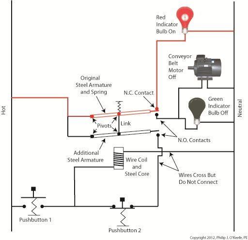
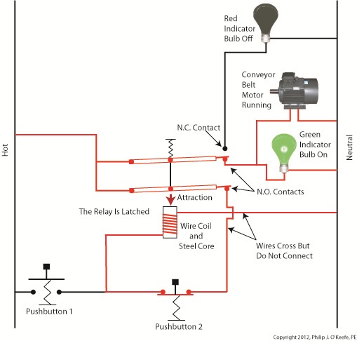
In our last blog we learned how a latched electric relay was unlatched at the push of a button, using red and green light bulbs to illustrate the control circuit. Now let’s see in Figure 1 how that circuit can be modified to include the control of an electric motor that drives, say, a conveyor belt inside a factory. Figure 1
Again, red lines in the diagram indicate parts of the circuit where electrical current is flowing. The relay is in its normal state, as discussed in a previous article, so the N.O. contacts are open and the N.C. contact is closed. No electric current can flow through the conveyor motor in this state, so it isn’t operating. Our green indicator bulb also does not operate because it is part of this circuit. However current does flow through the red indicator bulb via the closed N.C. contact, causing the red bulb to light. The red and green bulbs are particularly useful as indicators of the action taking place in the electric relay circuit. They’re located in the conveyor control panel along with Buttons 1 and 2, and together they keep the conveyor belt operator informed as to what’s taking place on the line, such as, is the belt running or stopped? When the red bulb is lit the operator can tell at a glance that the conveyor is stopped. When the green bulb is lit the conveyor is running. So why not just take a look at the belt itself to see what’s happening? Sometimes that just isn’t possible. Control panels are often located in central control rooms within large factories, which makes it more efficient for operators to monitor and control all operating equipment from one place. When this is the case, the bulbs act as beacons of the activity taking place on the line. Now, let’s go to Figure 2 to see what happens when Button 1 is pushed. Figure 2
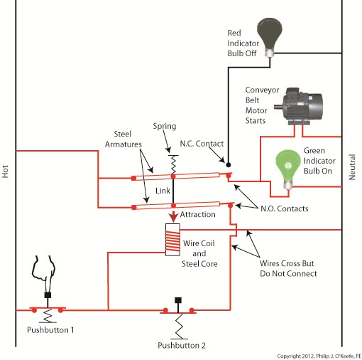
The relay’s wire coil becomes energized, causing the relay armatures to move. The N.C. contact opens and the N.O. contacts close, making the red indicator bulb go dark, the green indicator bulb to light, and the conveyor belt motor to start. With these conditions in place the conveyor belt starts up. Now, let’s look at Figure 3 to see what happens when we release Button 1. Figure 3
With Button 1 released the relay is said to be “latched” because current will continue to flow through the wire coil via one of the closed N.O. contacts. In this condition the red bulb remains unlit, the green bulb lit, and the conveyor motor continues to run without further human interaction. Now, let’s go to Figure 4 to see how we can stop the motor. Figure 4
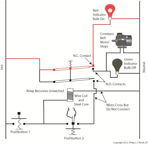
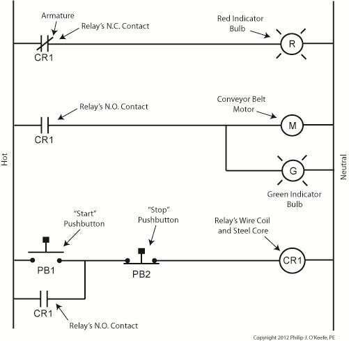
When Button 2 is depressed current flow through the relay coil interrupted. The relay is said to be unlatched and it returns to its normal state where both N.O. contacts are open. With these conditions in place the conveyor motor stops, and the green indicator bulb goes dark, while the N.C. contact closes and the red indicator bulb lights. Since the relay is unlatched and current no longer flows through its wire coil, the motor remains stopped even after releasing Button 2. At this point we have a return to the conditions first presented in Figure 1. The ladder diagram shown in Figure 5 represents this circuit. Figure 5
Next time we’ll introduce safety elements to our circuit by introducing emergency buttons and motor overload switches. ____________________________________________ |
Tags: blower, closed contact, control panel, control room, conveyor belt, electric current flow, electric motor, electric relay, engineering expert witness, equipment operator, factory, forensic engineer, indicator lamp, industrial control, ladder diagram, latched circuit, motor control, motor drive, N.C., N.O., normal state, normally closed, normally open, panel indicator, pump, push button, safety, start pushbutton, stop pushbutton
Posted in Engineering and Science, Expert Witness, Forensic Engineering, Innovation and Intellectual Property, Personal Injury, Product Liability, Professional Malpractice | Comments Off on Industrial Control Basics – Electric Motor Control
