| When I was a kid I had a toy robot that captured my attention like no other toy. I thought it was so cool to have something animated that looked both humanoid and machine-like at the same time. It couldn’t do much, just walk in a stiff, jerky way and move its arms up and down, but that was enough to keep me fascinated.
Today’s generation of robots do not often take on the humanoid form, but they’re capable of so much more. Robots on assembly lines perform a variety of tasks like welding and placing electronic components on circuit boards, and they do it much more quickly and accurately than any human could, so they’re often employed in manufacturing. We’ve been discussing the Production stage of the systems engineering approach to medical device design. We learned that within the manufacturing process there are often opportunities for cost reduction, and today we’ll see how robots can be used to reach those goals. Last week we presented a sample scenario involving the manufacture of a percussion therapy device. In their quest to reduce manufacturing costs, engineers identified bottlenecks along the assembly line which led to idle worker time and the inability to keep up with orders. In addition to these production woes, it was discovered that the tedious, repetitive manual labor that occurred at each bottleneck created opportunities for assembly mistakes. As many as 30 devices per day were being rejected by quality control inspectors due to issues such as faulty wiring and improper parts usage. This led to expensive rework to correct mistakes. After further evaluation, design engineers determine that bottlenecks can be eliminated by installing automated assembly equipment in the three distinct assembly stages represented on the line, those involving wiring harnesses, printed circuit boards, and the motor drive mechanism. The potential for human error is high during many facets of manufacturing, and this can be minimized or eliminated through the use of robots, that is to say, mechanized equipment capable of automatically performing a complex series of specific tasks. These robots never tire of performing tedious, repetitive work, and their efficiency is unparalleled. Their introduction at key junctures on the assembly line has benefits across the manufacturing process, enabling workers to keep continuously busy and reducing the incidence of human error. The introduction of robotics is known as industrial automation. Robots efficiently increase manufacturing speed, and along with it profits, so their introduction more than compensates for the investment costs associated with purchasing them. Next time we’ll continue our look at the Production stage to discover another way that systems engineering can simplifying the assembly process, by eliminating some functions altogether. ___________________________________________
|
Posts Tagged ‘electronic components’
Systems Engineering In Medical Device Design – Production, Part 3
Sunday, March 10th, 2013
Systems Engineering In Medical Device Design – Preproduction, Part I
Monday, February 4th, 2013| If you’ve been following along with our blog discussion on the systems engineering approach to medical device design, you should by now be convinced that instructions are important. In fact, the meticulous instructions produced during the manufacturing, operating, and maintenance phases of the Development stage are also crucial to later stages, that of Production and Utilization. Let’s finish up our discussion on the Development stage by taking a look at its final aspect, Preproduction.
The Preproduction aspect is instrumental to nipping potential problems in the bud before the medical devices go into actual production. In the initial Preproduction stages, systems engineers coordinate with the manufacturing and purchasing departments within the company as well as outside suppliers. The goal is to acquire all parts and equipment necessary to build a limited number of medical devices on the assembly line. Subjects such as preference in molded plastic components, motors, gears, pumps, springs, electronic components, circuit boards, wire, and tubing are discussed and agreed upon. Vendors are assessed with regard to their ability to produce parts when they are needed and that meet design specifications, satisfy quality requirements, and have costs that fall within budgetary constraints. The assembly of Preproduction devices provides an opportunity for systems engineers to validate manufacturing and quality control instructions and assess the device design with regard to manufacturability, meaning, the extent to which devices can be manufactured with relative ease, at minimal cost, while maintaining maximum reliability. Devices manufactured during this aspect of the Development stage serve as a test. Are instructions clearly written? Do the device parts fit together as they should? Are parts strong enough to withstand the assembly process? Can the devices be assembled as quickly and easily as expected? If the answer is “no” to any of these questions, then the device design and instructions must be returned to the design engineers and technical writers. Heads come together to rehash things and work out the bugs. Next time we’ll continue with the Preproduction aspect of the Development stage to see how laboratory and field testing enables systems engineers to shake out any more bugs from the medical device design, operating instructions, and maintenance instructions. ___________________________________________
|

Transistors – Voltage Regulation Part XIV
Monday, October 22nd, 2012|
As we’ve come to know through this series of blogs, all electronic components pose some degree of internal resistance to the electric current flowing through them. This resistance results in electrical energy being converted into heat energy, heat which poses potential problems to sensitive components like electronic circuit boards. If things get hot enough, components fail and fires may ignite. To address these issues engineers design circuits with resistors whose job it is to limit the current flowing to electrical components. In this article we’ll see how a limiting resistor protects a Zener diode from this fate, allowing it to continue doing its job of regulating voltage. In our last blog we applied Ohm’s Law to our regulated power supply circuit, which makes use of a Zener diode. See Figure 1. Figure 1
Ohm’s Law gave us the following equation to determine the amount of current, IPS, flowing from the unregulated power supply portion, through the current limiting resistor RLimiting, and making its way into the rest of the circuit: IPS = (VUnregulated – VZener) ÷ RLimiting We learned last week that for the circuit to work, the voltage of the unregulated power supply portion of the circuit, VUnregulated, must be greater than the Zener voltage, VZener. Looking at the equation above, we see that the voltage difference is divided by RLimiting, the value of the limiting resistor in the circuit. This limiting resistor is there to constrain the current flowing to the Zener diode, allowing the diode to keep things under control within the circuit. Basic mathematical principles hold that if a smaller number is divided by a bigger number, the resulting answer is an even smaller number. Applying this principle to the equation above, if RLimiting is a big number, then IPS must be a smaller number. On the other hand the smaller RLimiting gets, the bigger IPS becomes. So what does it take for our circuit to fail? Remove the limiting resistor as shown in Figure 2 and the value for RLimiting disappears. In other words, RLimiting becomes zero.
Figure 2
In this case our Ohm’s Law equation becomes: IPS = (VUnregulated – VZener) ÷ 0 = ∞ The resulting answer is said to go to infinity, or ∞, as it is represented mathematically. In other words, without a limiting resistor being employed within our circuit, IPS will become so large it will overwhelm the diode’s current handling capacity and lead to circuit failure. Next time we’ll go over some advantages and disadvantages of this Zener diode voltage regulating circuit, and why the disadvantages outweigh the advantages for many applications. ____________________________________________ |


Transistors – Voltage Regulation Part IV
Sunday, August 12th, 2012| We’ve all popped a circuit breaker sometime in our lives, often the result of making too heavy of an electrical demand in a single area of the house to which that circuit is dedicated. Like when you’re making dinner and operating the microwave, toaster, mixer, blender, food processor, and television simultaneously. The demand for current on a single circuit can be taxed to the max, causing it to pop the circuit breaker and requiring that trip to the electrical box to flip the switch back on.
Last time we began our discussion on unregulated power supplies and how they’re affected by power demands within their circuits. Our schematic shows there are two basic aspects to the circuit, namely, its direct current source, or VDC, and its internal resistance, RInternal. Now let’s connect the power supply output terminals to an external supply circuit through which electrical current will be provided to peripheral devices, much like all the kitchen gadgets mentioned above.
Figure 1
The external supply circuit shown in Figure 1 contains various electronic components, including electric relays, lights, and buzzers, and each of these has its own internal resistance. Combined, their total resistance is RTotal, as shown in our schematic. Current, notated as I, circulates through the power supply, through the external supply circuit, and then returns back to the power supply. The current circulates because the voltage, VDC, pushes it through the circuit like pressure from a pump causes water to flow through a pipe. RTotal and I can change, that is, increase or decrease, depending on how many components the microprocessor has turned on or off within the external supply circuit at any given time. When RTotal increases, electrical current, I, decreases. When RTotal decreases, electrical current I increases. Next time we’ll continue our discussion on Ohm’s Law, introduced last week, to show how the static effect of RInternal interacts with the changing resistance present in RTotal to adversely affect an unregulated power supply’s output voltage. ____________________________________________ |

Transistors – Digital Control Interface, Part I
Monday, June 18th, 2012| In the navy, the captain is the brains behind a ship’s operations. He gathers information, makes important decisions, then issues orders. He’s not there to roll up his sleeves and swab the decks. The captain relies on the ship’s officers to act as an interface between himself and the sailors that perform the physical labor required on deck.
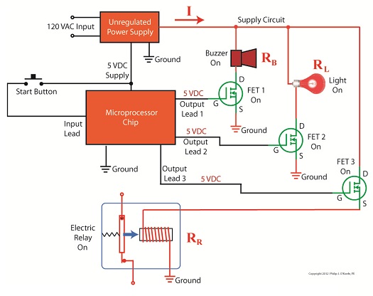
In this article we’ll see how the FET, that is, the field effect transistor, performs much the same role as the ship’s officers when it is used within electronic controls. There it acts as an interface between electronic components that issue commands and the electrical devices that carry them out. Last week we became familiar with field effect transistors and how their control of electrical current flow is analogous to how a faucet controls the flow of water. Although FETs can be used to vary the flow of current, they’re usually employed to perform a much simpler task, that of simply turning flow on or off, with no in-between modality. Like the captain of a ship, microprocessor and logic chips are the brains behind the operation in all sorts of industrial and consumer electronics. Figure 1 shows a few of them. Figure 1
The chips, which operate on low voltage, contain entire computer programs within them that gather information, make decisions, then instruct the higher voltage devices like motors, electrical relays, light bulbs, and audible alarms to follow. By “information,” I mean data signals received by the chip from its input connections to sensors, buttons, and other electrical components. This data informs the chip’s computer program of important operational information, like whether buttons have been pressed, switches are activated, and temperatures are normal. Based on this data, “decisions” are made by the chip using the logic contained within its program, then, depending on the decisions made, “commands” are issued by the chip. The commands, in the form of electrical output signals, are put into action by the work horses, the higher voltage devices. They, like a ship’s sailors, perform the actual physical work. There is one problem presented by this scenario, however. The electric output signals from the lower voltage chips are not suited to directly control the higher voltage devices because the signal voltage put out by the chips is too low. Even if the chip was designed to work at a higher voltage, the high level of current drawn by the motors, relays, and bulbs would lead to damage of the delicate circuitry within the chip. The chips must therefore rely on the FET to act as a digital control interface between them and the higher voltage devices, much as the ship’s captain depends on his subordinates to carry out his orders. Next week we’ll look at a real life example of how a digital interface is put into operation within an industrial product.
____________________________________________ |


