| Not too long ago I was retained as an engineering expert to testify on behalf of a plaintiff who owned a sports bar. The place was filled with flat screen televisions that were plugged into 120 volt alternating current (VAC) wall outlets. To make a long story short, the electric utility wires that fed power to the bar were hit by a passing vehicle, causing the voltage in the outlets to increase well beyond what the electronics in the televisions could handle. The delicate electronics were not suited to be connected with the high voltage that suddenly surged through them as a result of the hit, and they overloaded and failed.
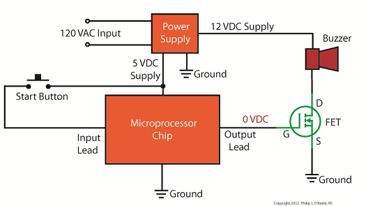
Similarly, lower voltage microprocessor and digital logic chips are also not suited to directly connect with higher voltage devices like motors, electrical relays, and light bulbs. An interface between the two is needed to keep the delicate electronic circuits in the chips from overloading and failing like the ill fated televisions in my client’s sports bar. Let’s look now at how a field effect transistor (FET) acts as the interface between low and high voltages when put into operation within an industrial product. I was once asked to design an industrial product, a machine which developed medical x-ray films, utilizing a microprocessor chip to automate its operation. The design requirements stated that the product be powered by a 120 VAC, such as that available through the nearest wall outlet. In terms of functionality, upon startup the microprocessor chip was to be programmed to first perform a 40-minute warmup of the machine, then activate a 12 volt direct current (VDC) buzzer for two seconds, signaling that it was ready for use. This sequence was to be initiated by a human operator depressing an activation button. The problem presented by this scenario was that the microprocessor chip manufacturer designed it to operate on a mere 5 VDC. In additional, it was equipped with a digital output lead that was limited in functionality to either “on” or “off” and capable of only supplying either extreme of 0 VDC or 5 VDC, not the 12 VDC required by the buzzer. Figure 1 illustrates my solution to this voltage problem, although the diagram shown presents a highly simplified version of the end solution. Figure 1The illustration shows the initial power supplied at the upper left to be 120 VAC. This then is converted down to 5 VDC and 12 VDC respectively by a power supply circuit. The 5 VDC powers the microprocessor chip and the 12 VDC powers the buzzer. The conversion from high 120 VAC voltage to low 5 and 12 VDC voltage is accomplished through the use of a transformer, a diode bridge, and special transistors that regulate voltage. Since this article is about FETs, we’ll discuss transistor power supplies in more depth in a future article. To make things a little easier to follow, the diagram in Figure 1 shows the microprocessor chip with only one input lead and one output lead. In actuality a microprocessor chip can have dozens of input and output leads, as was the case in my solution. The input leads collect information from sensors, switches, and other electrical components for processing and decision making by the computer program contained within the chip. Output leads then send out commands in the form of digital signals that are either 0 VDC or 5 VDC. In other words, off or on. The net result is that these signals are turned off or on by the program’s decision making process. Figure 1 shows the input lead is connected to a pushbutton activated by a human. The output lead is connected to the gate (G) of the FET. The FET is shown in symbolic form in green. The FET drain (D) lead is connected to the buzzer and its source (S) lead terminates in connection to electrical ground to complete the electrical circuit. Remember, electric current naturally likes to flow from the supply source to electrical ground within circuits, and our scenario is no exception. Next time we’ll see what happens when someone presses the button to put everything into action.
____________________________________________ |
Posts Tagged ‘high voltage’
Transistors – Digital Control Interface, Part I
Monday, June 18th, 2012| In the navy, the captain is the brains behind a ship’s operations. He gathers information, makes important decisions, then issues orders. He’s not there to roll up his sleeves and swab the decks. The captain relies on the ship’s officers to act as an interface between himself and the sailors that perform the physical labor required on deck.
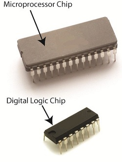
In this article we’ll see how the FET, that is, the field effect transistor, performs much the same role as the ship’s officers when it is used within electronic controls. There it acts as an interface between electronic components that issue commands and the electrical devices that carry them out. Last week we became familiar with field effect transistors and how their control of electrical current flow is analogous to how a faucet controls the flow of water. Although FETs can be used to vary the flow of current, they’re usually employed to perform a much simpler task, that of simply turning flow on or off, with no in-between modality. Like the captain of a ship, microprocessor and logic chips are the brains behind the operation in all sorts of industrial and consumer electronics. Figure 1 shows a few of them. Figure 1
The chips, which operate on low voltage, contain entire computer programs within them that gather information, make decisions, then instruct the higher voltage devices like motors, electrical relays, light bulbs, and audible alarms to follow. By “information,” I mean data signals received by the chip from its input connections to sensors, buttons, and other electrical components. This data informs the chip’s computer program of important operational information, like whether buttons have been pressed, switches are activated, and temperatures are normal. Based on this data, “decisions” are made by the chip using the logic contained within its program, then, depending on the decisions made, “commands” are issued by the chip. The commands, in the form of electrical output signals, are put into action by the work horses, the higher voltage devices. They, like a ship’s sailors, perform the actual physical work. There is one problem presented by this scenario, however. The electric output signals from the lower voltage chips are not suited to directly control the higher voltage devices because the signal voltage put out by the chips is too low. Even if the chip was designed to work at a higher voltage, the high level of current drawn by the motors, relays, and bulbs would lead to damage of the delicate circuitry within the chip. The chips must therefore rely on the FET to act as a digital control interface between them and the higher voltage devices, much as the ship’s captain depends on his subordinates to carry out his orders. Next week we’ll look at a real life example of how a digital interface is put into operation within an industrial product.
____________________________________________ |
Further Inside the Wall Wart
Sunday, September 11th, 2011| What do wall warts, aka AC wall adapters, and microwave ovens have in common? Well, in previous blogs discussing microwaves, we saw how a microwave oven’s high voltage circuitry uses a transformer, diode, and capacitor to effectively convert AC voltage into DC voltage. Wall warts do much the same thing and in very much the same way.
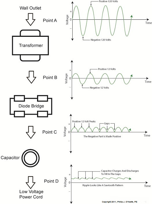
If you will recall from our discussion of microwave ovens in the past few weeks, the transformer in a high voltage circuit transforms 120 volts into a much higher voltage, say 4000 volts, in order to make things work. The diode and capacitor within both the microwave and the wall wart are key to facilitating this magical act, but in the wall wart it happens at a much lower voltage, about 12 volts. Last week we began exploring the inner workings of the wall wart. We discovered how its transformer converts the 120 volts emanating from your average wall outlet to the 12 volts required by most electronic devices. These voltages are shown at Points A and B in Figure 1 below. The fact that the voltage being put out results in waves of energy which alternate between a positive maximum value, zero, and a negative maximum value, makes it an unacceptable power source for most electronic devices. They require voltage that doesn’t alternate, and this is where the wall wart’s diode bridge and capacitor come into play. Figure 1 – The Workings of the Wall Wart Transformer The wall wart’s diode bridge consists of four electronic components, namely the diodes, which are connected together. This diode bridge goes a bit further than the single diode present in a microwave oven, because it doesn’t merely eliminate negative aspects of alternating voltage. It actually transforms negative voltage into positive voltage. The result is a series of 12 volt peaks as shown at Point C of Figure 1. In fact, we end up with twice as many voltage peaks, and this is important, as you’ll see below. We still have the problem of zero voltage gaps to address. You see, over time the voltage at Point C of Figure 1 keeps changing between 0 volts and positive 12 volts. This can lead to problems, because many electronic devices require a consistent voltage of greater than zero to operate properly. For example, a light emitting diode (LED) might develop an annoying flicker, or you might end up hearing an irritating hum while listening to the radio. These annoyances are virtually eliminated by feeding voltage from the diode bridge into the capacitor, which gets rid of the zero voltage gaps between the voltage peaks. Like a microwave’s capacitor, the one within a wall wart charges up with electrical energy as the voltage from the diode bridge nears the top of a peak. Then, as voltage begins its dive back to a zero value, the capacitor discharges its electrical energy to fill in the gaps between peaks. The result is the rippled voltage pattern at Point D of Figure 1. With the gaps filled in, the voltage is at, or close enough to, the 12 volts required to keep an electronic device operating properly when it is connected to the wall wart’s low voltage power cord. Well, that’s it for our look at the wall warts that power our myriad of electronic devices. Next time we’ll switch to a totally topic and look at some of the basics of food manufacturing equipment design. ____________________________________________ |
Electrocution by Microwave Oven
Sunday, August 21st, 2011|
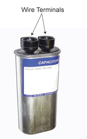
Ever been jolted with electric current? Like the time you’d just gotten out of the shower and went to plug in a lamp with damp hands? So what do you think the voltage was that caused that nasty biting feeling that resulted from your momentary lapse in good judgment? Once, while operating a subway car at a railroad museum at which I was a member, I was inadvertently “electrocuted.” I went to turn on the lights inside the car, and unbeknownst to me the light switch was faulty. When I touched it I instantly became connected to the car’s 600 volt lighting circuit. With just a split second of contact the current passed through the tip of my right index finger, along my right arm, down the right side of my body, and out the tip of my big toe, finally exiting into the metal railcar’s body. The current actually burned a hole where it had exited through my boot. The experience was both frightening and painful, but fortunately did not result in any real injury. I was lucky that the current had bypassed my heart, because if it hadn’t, I might not be alive today. That was 600 volts. Now imagine being jolted by the 4000 volts present in a microwave oven’s internal high voltage circuitry. Last week we discovered how the high voltage circuit in a microwave oven converts the ordinary, everyday 120 volts alternating current (AC) present in our homes into a much higher voltage approximating direct current (DC). This is done by an internal component known as the capacitor. The capacitor is capable of storing large amounts of electrical energy, and this can result in microwave ovens presenting a danger even when unplugged. A microwave oven capacitor is shown in Figure 1. If you happened to touch its wire terminals while it’s still charged, its power can rapidly discharge high voltage electrical current throughout your body. The electrical current from the capacitor can even stop your heart from beating, and this is exactly what caused the demise of a person featured on a soon to be released Discovery Channel program, Curious and Unusual Deaths. While being interviewed as an expert for the program, I was asked to explain this rather unique phenomenon of latent stored energy, and how it may present a threat. Figure 1 – A Microwave Oven Capacitor Remember, a microwave oven capacitor can remain charged with dangerous electrical energy for hours, even days, after the microwave oven plug is pulled from the wall outlet. The bottom line here is that you should not attempt to fix your microwave oven, unless you are trained and certified to do so. Next week we’ll switch to a different topic, namely an electrical device known as a “wall wart.” That’s the black plastic adapter you plug into electrical outlets to power your cell phones, laptops, and other small electronics. ____________________________________________ |
The Microwave Oven — More on How AC Becomes DC
Monday, August 15th, 2011| The world of electricity is full of mysteries and often unanticipated outcomes, and if you’ve been reading along with my blog series you have been able to appreciate and come to some understanding of a fair number of them. This week’s installment will be no exception.
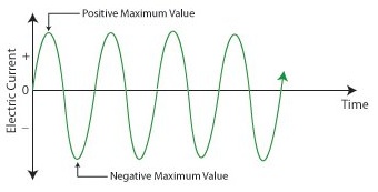
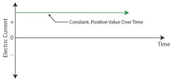
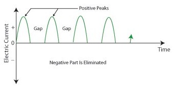
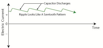
Last week we looked briefly at the high voltage circuit within a microwave oven. We discovered that the circuit contains a transformer that raises 120 volts alternating current (AC) to a much higher voltage, around 4000 volts AC. The circuit then transforms the AC into direct current (DC) with the help of electronic components known as a diode and capacitor. Let’s take a closer look at how the diode and capacitor work together to make AC into DC. Let’s follow an AC wave with the aid of a device called an oscilloscope. An oscilloscope takes in an electronic signal, measures it, graphs it, and shows it on a display screen so you can see how the signal changes over time. An AC wave is shown in Figure 1 as it would appear on an oscilloscope. Figure 1 – Alternating Current Wave You can see that each wave cycle starts with a zero value, climbs to a positive maximum value, then back to zero, and finally back down to a maximum negative value. The current keeps alternating between positive and negative polarity, hence the name “alternating current.” Within the microwave oven’s high voltage circuitry the transformer does the job of changing, or transforming if you will, 120 volts AC into 4000 volts AC. This high voltage is needed to make electrons leave the cathode in the magnetron and move them towards the anode to generate microwaves. But we’re not done with the transformation process yet. The magnetron requires DC to operate, not AC. DC current remains constant over time, maintaining a consistent positive value as shown in Figure 2. It is this type of consistency that the magnetron needs to operate. Figure 2 – Direct Current The microwave’s diode and capacitor work together to convert the 4000 volts AC into something which resembles 4000 volts DC. First the diode acts like a one-way valve, passing the flow of positive electric current and blocking the flow of negative current. It effectively chops off the negative part of the AC wave, leaving only positive peaks, as shown in Figure 3. Figure 3 – The Diode Chops Off The Negative Part of the AC Wave Between the peaks are gaps where there is zero current, and this is when the capacitor comes into play. Capacitors are similar to batteries because they can be charged with electrical energy and then discharge that energy when needed. Unlike a battery, the capacitor charges and discharges very quickly, within a fraction of a second. Within the circuitry of a microwave oven the capacitor charges up at the top of each peak in Figure 3, then, when the current drops to zero inside the gaps the capacitor comes into play, discharging its electrical energy into the high voltage circuit. The result is an elimination of the zero current gaps. The capacitor acts as a reserve energy supply to fill in the gaps between the peaks and keep current continually flowing to the magnetron. We have now witnessed a mock DC current situation being created, and the result is shown in Figure 4. Figure 4 – The Capacitor Discharges to Fill In The Gaps Between Peaks The output of this approximated DC current looks like a sawtooth pattern instead of the straight line of a true DC current shown in Figure 2. This ripple pattern is evidence of the “hoax” that has been played with the AC current. The net result is that the modified AC current, thanks to the introduction of the diode and energy storing capacitor, has made an effective enough approximation of DC current to allow our magnetron to get to work jostling electrons loose from the cathode and putting our microwave oven into action. You now have a basic understanding of how to turn AC into an effective approximation of DC current. Next week we’ll find out how this high voltage circuit can prove to be lethal, even when the microwave oven is unplugged. ____________________________________________ |
The Heart of the Microwave Oven
Monday, July 18th, 2011| In the world of inventions it happens with some regularity that an invention to do one thing unexpectedly leads to a device that does something completely different. Take for example Edison’s phonograph. At the time, he was working on an invention to record the dots and dashes of Morse code telegraph messages so they could be sent out repeatedly without an operator having to tap them out each time and possibly making mistakes while doing so. Little did he know that this would lead to the evolvement of the phonograph and recording industries.
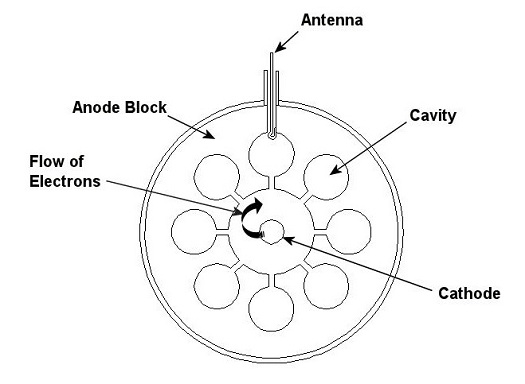
Another invention “by mistake” took place when the resonant cavity magnetron, originally developed for use with microwave radar, led to the development of the microwave oven. Last week we talked about how long wave radar, the first type of radar to be developed, was effectively used by the British to repel enemy air attacks during World War II. But long wave radar was large and cumbersome to employ, and it soon evolved into an improved version, the shorter wave, or, as we know it, microwave radar. So what is this resonant cavity magnetron that led to its creation? A pop bottle can give us a clue. Blow across the top of an empty glass pop bottle (or soda bottle, depending on the part of the country you’re from) and a familiar resonant sound results. The sound is created by an effect known as cavity resonance, and other bona fide musical instruments make use of this phenomenon to produce musical sounds. How this works is that where a cavity exists, when air molecules are introduced into it, the molecules are caused to resonate in and out of the cavity many times per second. This creates a sound at a certain frequency, that frequency depending on the shape and dimensions of the cavity, as well as the size of its opening. The resonant cavity magnetron, or magnetron for short, is actually a high powered vacuum tube that operates in a very similar fashion to a pop bottle, or any other musical device making use of a cavity, but instead of using air molecules to generate sound waves, it uses electrons to generate short wavelength radio waves, called microwaves. The magnetron contains a series of cavities that are arranged in a circle with the openings pointing inward towards the center, as shown in Figure 1. Figure 1 – Interior View of a Resonant-Cavity Magnetron Next week we’ll see what this interesting looking device has in common with the simple act of blowing air across the top of a pop bottle and what this all has to do with microwaves. _____________________________________________ |
Ground Fault Circuit Interrupters
Sunday, June 26th, 2011| I’ve been talking about how I was asked to be a subject matter expert for an upcoming series on The Discovery Channel titled Curious and Unusual Deaths. Most of the accidents discussed involved electrocutions, and in each case the electrocution occurred because the victim’s body, usually their hand, inadvertently contacted a source of current. When that happened their bodies essentially became like a wire, providing an unintended path for current to travel on its way to the ground. Why does it travel to the ground, you ask? Because electric current, by its very nature, always wants to flow along a conductor of electricity from a higher voltage to a lower voltage. The ground is the lowest voltage area on our planet. When electricity flows to ground along an unintended path it’s referred to as a “ground fault,” because that’s where the electricity is headed, to the ground, or Earth. By “fault” I mean that something in an electrical circuit is broken or not right, allowing the electrical current to leak out of the circuit along an unintended path, like through a person’s body.
For example, in one of the Curious and Unusual Deaths segments I was asked to explain how a fault in wiring caused electrical current to flow through a woman’s body to the ground that she was standing on. This happened when she unintentionally came in contact with a metal door that was, unbeknownst to her, electrically charged from an unanticipated source. The current was strong enough to cause her death. Where did the electric current originate from? Watch the program to find out, but I’m sure you’d never guess. To say that it was an unlikely source is an understatement. When ground faults pass through a person’s body, bad things often happen, ranging from a stinging shock to stopping your heart muscle to burning you from the inside out. The severity depends on a number of factors, including the strength of the current to the amount of time your body is exposed to it. It might surprise you to know that if your skin is wet at the time of contacting a current, you risk a greater chance of injury. Water, from most sources, contains dissolved minerals, making it a great conductor of electricity. But what exactly is electrical current? Scientifically speaking it’s the rate of flow of electrons through a conductor of electricity. Let’s take a closer look at a subject close to home, a power cord leading from a wall’s outlet to the electric motor in your kitchen hand mixer. That power cord contains two wires. In the electrical world one wire is said to be “hot” while the other is “neutral.” The mixer whirrs away while you whip up a batch of chocolate frosting because electrons flow into its motor from the outlet through the hot wire, causing the beaters to spin. The electrons then safely flow back out of the motor to the wall outlet through the neutral wire. Now normally the number of electrons flowing into the motor through the hot wire will basically equal the number flowing out through the neutral wire, and this is a good thing. When current flow going in equals current flow going out, we end up enjoying a delicious chocolate cake. Since the human body can conduct electricity, serious consequences may result if there is an electrical defect in our hand mixer that creates a ground fault through the operator’s body while they are using it. In that situation the flow of electrons coming into the mixer from the hot wire will begin to flow through the operator’s body rather than flowing through the neutral wire. The result is that the number of electrons flowing through the hot wire does not equal the flow of electrons flowing through the neutral wire. Electrons are leaking out of what should be a closed system, entering the operator’s body instead while on its way to find the ground. Next time we’ll look at a handy device called a Ground Fault Circuit Interrupter (GFCI) and how it keeps an eye on the flow of electrons, which in turn keeps us safe from being electrocuted. _____________________________________________ |
Transformers – Electric Utility Power Savers
Sunday, January 2nd, 2011| Each day millions of Americans start their mornings with coffee, brewed in a coffee maker, and a microwaved breakfast. They flick on the light and exhaust fan before starting their showers and blow dry their hair afterwards. Each of these acts of modern living is a small miracle. And if you’re like most people you can’t see the power plant supplying the power to your modern conveniences from your home, and how the electricity travels from the plant to you isn’t too clear.
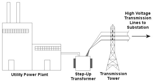
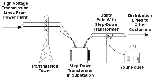
Truth is the process of supplying our homes with power isn’t as straightforward as you might think, and the actual transmission of that power isn’t straightforward at all. To begin with, the wires used in power lines are less than perfect conductors of electricity. Along any given length of wire there are all sorts of imperfections in the metal, and these tend to resist the flow of electrical current. These imperfections will always exist to some extent, even with the best manufacturing techniques and quality control, and the longer the power line, the more resistance the power flow will meet. The result is loss of electrical power. If there weren’t some kind of compensatory action at work to rectify this, your morning routine wouldn’t be nearly so smooth. To address the problem of power loss electric utilities use step-up transformers, similar to the one in Figure 1. This enables voltage produced by the generator at the plant to be raised to a higher voltage, in turn enabling it to travel longer distances and remain effective. Figure 1 – Electricity Leaving the Power Plant Goes Through a Step-Up Transformer For example, let’s say that an electric generator puts out 12,000 volts, and a step-up transformer raises that to 765,000 volts, enabling transmission to customers far away. If you will recall from last week’s blog, with electrical transformers, there is an inverse relationship between voltage and current. So, when a step-up transformer increases input voltage, it actually results in a lowering of electrical current. So how does this phenomenon aid in power transmission? Simply put, when there is less current flowing through the wires, there is an accompanying reduction in power loss over the long length of the transmission line. Let’s take a look at what happens when the power reaches our homes. Figure 2 shows a simplified distribution route from the power plant. Figure 2 – A Step-Down Transformer is Used to Supply Electric Utility Customers First, the higher voltage originating from the step-up transformer at the power plant is decreased by the use of a step-down transformer located in a substation many miles away at the other end of the transmission line. The use of this intermediary step-down transformer effectively lowers the voltage and at the same time raises the current at the other end of the line, the end where customers like you and I are waiting to use our hair dryers unimpeded. The path that the power follows is somewhat circuitous, but well planned out, with numerous strategically positioned distribution lines acting as the final leg of delivery. These distribution lines do what their name implies, they weave their way along streets and alleys, finally distributing electricity to customers. A step-down transformer located in a substation along the power transmission route allows this all to happen. It can readily convert the 765,000 volts being sent by the power plant to the 25,000 volts needed to feed distribution power lines. These, in turn, power individual homes, hospitals, etc. Now you obviously can’t plug a television into a 25,000 volt wall outlet located in your house, so another step-down transformer is required to temper it into power that’s both usable and safe. The one in our diagram is mounted on a nearby utility pole, and its job is to lower the 25,000 volts which it receives into a more manageable 240 and 120 volts, which is then fed into your home. That wraps up our series on electrical transformers. Perhaps the next time you flip that switch in your home, whether it be on your hair dryer, TV, or what have you, you’ll pause for a moment to reflect on the long path it has followed to make your life just a little bit easier. _____________________________________________
|
