|
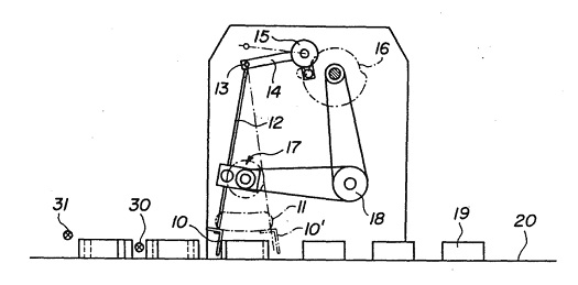
Movies, that is 3D animations, are moving into the courtroom, and intended messages are made clearer than ever as a result. If a picture is worth a thousand words, how much more effective is a moving 3D image? We’ve been viewing a static two-dimensional representation of a machine for the past two blogs. Have you been able to figure it out yet? Here it is again:
Would it help you to understand if I identified it as a piece of food manufacturing equipment equipped with a rake that aligns cookies on a conveyor belt? Would that verbal description allow you to “see” in your mind’s eye how it operates? Unless you had the right technical background, it’s unlikely. Last week we introduced the verbiage person of ordinary skill in the art as a term widely used within patent litigation. This person is said to have the ability to interpret and understand patent drawings, and they typically possess a technical and/or scientific background. But what if participants in a legal proceeding lack this background? Technical experts are often hired on as consultants to attorneys, and in some instances, judges, when clarification is required. These experts provide technical expertise and tutorials on the technology involved in complex cases, and it happens with regularity when the operation of a patented device is in question. By employing 3D animations the expert can show how the device operates, rather than attempt to explain it using the technical language of their profession. The expert works closely with an animation artist to create the animation, providing the technical information that the animator will use to create the fully functional model. Animators do not typically have the technical background to accomplish this on their own and will require an ongoing dialog with the technical expert to create the animation. And now the moment we’ve all been waiting for. Here is our static image brought to life through animation:
The animation commands the viewer’s attention and holds their interest, even if they have no background in engineering or science, and the device’s function is now made clear. It must be noted that in the patent drawing, part of the mechanism lies in front of a steel divider plate and part behind, but for purposes of clarity the entire mechanism has been shown to the front of the plate. Now there’s no doubt as to how the parts move together to even up the rows of cookies on the conveyor belt. Next week we’ll talk about juries, perception, and the advantages of using courtroom animations when at trial. |
Posts Tagged ‘food manufacturing equipment’
Courtroom Animations – Bringing Patents to Life
Monday, June 17th, 2013Patent Drawings
Sunday, June 2nd, 2013|
I remember the first time I saw a blueprint. It was during high school shop class where we learned how to use power tools to make the wooden chairs, tables, and chests shown in blueprints. I was completely confused. The odd paper and blue print, coupled with the liberal use of unfamiliar symbols, dashes and dots, and what appeared to be a mind boggling amount of detail was enough to start me in a cold sweat. For many people, patent drawings are a lot like that first blueprint I saw. As a static two-dimensional (2D) representation of an operational device which is often complex, they present an immense amount of information on a page. The average person would be hard pressed to interpret them, and in fact, as we’ll learn later, they aren’t supposed to be able to. We’ve been talking about patent basics in this series of blogs, and we’ll continue that discussion in the following weeks with a concentration on patent drawings. In the meantime, here’s one to ponder. When you look at a patent drawing like the one below, what do you see? What do you think this thing is and what is it supposed to do? We’ll find out next week…
___________________________________________ |
Food Manufacturing Challenges – HACCP Design Principle No. 2
Sunday, October 23rd, 2011| What would you do if you heard an unfamiliar sound coming from your water heater? If you’re like most people you’d make a mental note to keep an eye on it, but ignore it for the most part. Unfortunately, this less than proactive approach often results in water heater floods. As an engineer, I’m more likely than the general population to investigate the cause of the water heater’s sound and proactively seek a remedy before a real problem has a chance to develop.
The FDA’s Hazard Analysis Critical Control Point (HACCP) seeks to accomplish the same with regard to food production. As discussed last week with regard to HACCP Principle 1, those involved in designing food processing equipment must proactively analyze designs to identify potential food safety hazards. Now let’s see how common sense is once again employed through Principle 2, guiding design engineers to take control of situations where hazards have been identified through Principle 1. HACCP Principle 2: Identify critical control points. A critical control point (CCP) is a step in the design process at which a control can be most effectively introduced to prevent or eliminate hazards. In this context a “control” would be a design revision to eliminate hazards identified during the Principle 1 stage. We will once again use the two examples introduced in last week’s blog discussion on Principle 1. In our first example, hazard analysis revealed that food can accumulate in a food processing machine in areas where cleaning is difficult or impossible. This accumulation would eventually rot and fall into uncontaminated food passing through production lines. Design engineers would work to address this contamination hazard by identifying a CCP within the design process, that is, the best place where a preventative measure can be added to the machine setup to facilitate removal of the accumulation. At that CCP, measures can be taken to change the machine’s design. Perhaps all that is needed to correct the situation is to include easy to remove access covers. In our second example hazard analysis revealed that the metal tooling as designed for our food production machine was too fragile and would not withstand the repeated forces imposed on it by the mass production process. This design flaw presents a strong possibility that metal parts will break off and enter food on the line. To correct this situation, design engineers must once again identify the juncture within the design process at which a CCP is identified. There, a preventative measure can most effectively be introduced, enabling more robust metal to be used in the tooling. The previous two examples illustrate CCPs being utilized within the design process. CCPs can also be introduced outside the design process, as when they are identified during the course of training procedures involving the operation, cleaning, and general maintenance of equipment and production lines. And an excellent way of implementing this approach is to have design engineers collaborate with operating and maintenance staff. Working together, they are best able to identify key elements to be addressed and make note of them within written procedures. Now that we have identified some examples of CCPs within the design process, we can move on to HACCP Principle 3 and how it guides design engineers to establish critical limits for each CCP.
|
Further Inside the Wall Wart
Sunday, September 11th, 2011| What do wall warts, aka AC wall adapters, and microwave ovens have in common? Well, in previous blogs discussing microwaves, we saw how a microwave oven’s high voltage circuitry uses a transformer, diode, and capacitor to effectively convert AC voltage into DC voltage. Wall warts do much the same thing and in very much the same way.
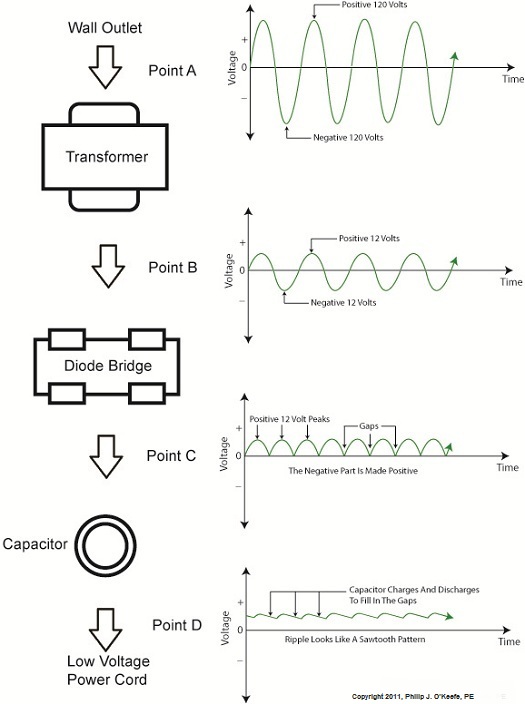
If you will recall from our discussion of microwave ovens in the past few weeks, the transformer in a high voltage circuit transforms 120 volts into a much higher voltage, say 4000 volts, in order to make things work. The diode and capacitor within both the microwave and the wall wart are key to facilitating this magical act, but in the wall wart it happens at a much lower voltage, about 12 volts. Last week we began exploring the inner workings of the wall wart. We discovered how its transformer converts the 120 volts emanating from your average wall outlet to the 12 volts required by most electronic devices. These voltages are shown at Points A and B in Figure 1 below. The fact that the voltage being put out results in waves of energy which alternate between a positive maximum value, zero, and a negative maximum value, makes it an unacceptable power source for most electronic devices. They require voltage that doesn’t alternate, and this is where the wall wart’s diode bridge and capacitor come into play. Figure 1 – The Workings of the Wall Wart Transformer The wall wart’s diode bridge consists of four electronic components, namely the diodes, which are connected together. This diode bridge goes a bit further than the single diode present in a microwave oven, because it doesn’t merely eliminate negative aspects of alternating voltage. It actually transforms negative voltage into positive voltage. The result is a series of 12 volt peaks as shown at Point C of Figure 1. In fact, we end up with twice as many voltage peaks, and this is important, as you’ll see below. We still have the problem of zero voltage gaps to address. You see, over time the voltage at Point C of Figure 1 keeps changing between 0 volts and positive 12 volts. This can lead to problems, because many electronic devices require a consistent voltage of greater than zero to operate properly. For example, a light emitting diode (LED) might develop an annoying flicker, or you might end up hearing an irritating hum while listening to the radio. These annoyances are virtually eliminated by feeding voltage from the diode bridge into the capacitor, which gets rid of the zero voltage gaps between the voltage peaks. Like a microwave’s capacitor, the one within a wall wart charges up with electrical energy as the voltage from the diode bridge nears the top of a peak. Then, as voltage begins its dive back to a zero value, the capacitor discharges its electrical energy to fill in the gaps between peaks. The result is the rippled voltage pattern at Point D of Figure 1. With the gaps filled in, the voltage is at, or close enough to, the 12 volts required to keep an electronic device operating properly when it is connected to the wall wart’s low voltage power cord. Well, that’s it for our look at the wall warts that power our myriad of electronic devices. Next time we’ll switch to a totally topic and look at some of the basics of food manufacturing equipment design. ____________________________________________ |


