| When my daughter was seven she found out about Ohm’s Law the hard way, although she didn’t know it. She had accidentally bumped into her electric toy train, causing its metal wheels to derail and fall askew of the metal track. This created a short circuit, causing current to flow in an undesirable direction, that is, through the derailed wheels rather than along the track to the electric motor in the locomotive as it should.
What happened during the short circuit is that the bulk of the current began to follow through the path of least resistance, that of the derailed wheels, rather than the higher resistance of the electric motor. Electric current, always opportunistic, will flow along its easiest course, in this case the short, thick metal of the wheels, rather than work its way along the many feet of thin metal wire of the motor’s electromagnetic coils. With its wheels sparking at the site of derailment the train had become an electric toaster within seconds, and the carpet beneath the track began to burn. Needless to say, mom wasn’t very happy. In this instance Ohm’s Law was at work, with a decidedly negative outcome. The Law’s basic formula concerning the toy train would be written as: I = V ÷ Rwhere, I is the current flowing through the metal track, V is the track voltage, and R is the internal resistance of the metal track and locomotive motor, or in the case of a derailment, the metal track and the derailed wheel. So, according to the formula, for a given voltage V, when the R got really small due to the derailment, I got really big. But enough about toy trains. Let’s see how Ohm’s Law applies to an unregulated power supply circuit. We’ll start with a schematic of the power supply in isolation.
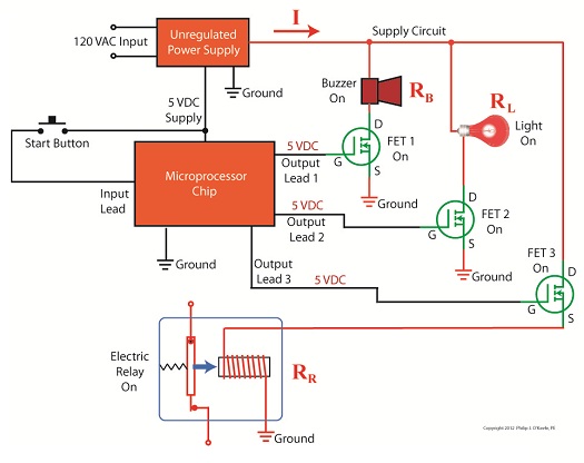
Figure 1The unregulated power supply shown in Figure 1 has two basic aspects to its operation, contained within a blue dashed line. The dashed line is for the sake of clarity when we connect the power supply up to an external circuit which powers peripheral devices later on. The first aspect of the power supply is a direct current (DC) voltage source, which we’ll call VDC. It’s represented by a series of parallel lines of alternating lengths, a common representation within electrical engineering. And like all electrical components, the power supply has an internal resistance, such as discussed previously. This resistance, notated RInternal, is the second aspect of the power supply, represented by another standard symbol, that of a zigzag line. Finally, the unregulated power supply has two output terminals. These will connect to an external supply circuit through which power will be provided to peripheral devices. Next time we’ll connect to this external circuit, which for our purposes will consist of an electric relay, buzzer, and light to see how it all works in accordance with Ohm’s Law. ____________________________________________ |
Posts Tagged ‘DC’

Further Inside the Wall Wart
Sunday, September 11th, 2011| What do wall warts, aka AC wall adapters, and microwave ovens have in common? Well, in previous blogs discussing microwaves, we saw how a microwave oven’s high voltage circuitry uses a transformer, diode, and capacitor to effectively convert AC voltage into DC voltage. Wall warts do much the same thing and in very much the same way.
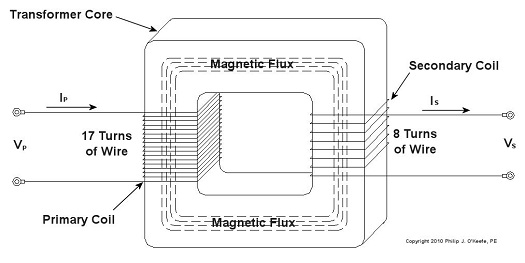
If you will recall from our discussion of microwave ovens in the past few weeks, the transformer in a high voltage circuit transforms 120 volts into a much higher voltage, say 4000 volts, in order to make things work. The diode and capacitor within both the microwave and the wall wart are key to facilitating this magical act, but in the wall wart it happens at a much lower voltage, about 12 volts. Last week we began exploring the inner workings of the wall wart. We discovered how its transformer converts the 120 volts emanating from your average wall outlet to the 12 volts required by most electronic devices. These voltages are shown at Points A and B in Figure 1 below. The fact that the voltage being put out results in waves of energy which alternate between a positive maximum value, zero, and a negative maximum value, makes it an unacceptable power source for most electronic devices. They require voltage that doesn’t alternate, and this is where the wall wart’s diode bridge and capacitor come into play.
Figure 1 – The Workings of the Wall Wart Transformer The wall wart’s diode bridge consists of four electronic components, namely the diodes, which are connected together. This diode bridge goes a bit further than the single diode present in a microwave oven, because it doesn’t merely eliminate negative aspects of alternating voltage. It actually transforms negative voltage into positive voltage. The result is a series of 12 volt peaks as shown at Point C of Figure 1. In fact, we end up with twice as many voltage peaks, and this is important, as you’ll see below. We still have the problem of zero voltage gaps to address. You see, over time the voltage at Point C of Figure 1 keeps changing between 0 volts and positive 12 volts. This can lead to problems, because many electronic devices require a consistent voltage of greater than zero to operate properly. For example, a light emitting diode (LED) might develop an annoying flicker, or you might end up hearing an irritating hum while listening to the radio. These annoyances are virtually eliminated by feeding voltage from the diode bridge into the capacitor, which gets rid of the zero voltage gaps between the voltage peaks. Like a microwave’s capacitor, the one within a wall wart charges up with electrical energy as the voltage from the diode bridge nears the top of a peak. Then, as voltage begins its dive back to a zero value, the capacitor discharges its electrical energy to fill in the gaps between peaks. The result is the rippled voltage pattern at Point D of Figure 1. With the gaps filled in, the voltage is at, or close enough to, the 12 volts required to keep an electronic device operating properly when it is connected to the wall wart’s low voltage power cord. Well, that’s it for our look at the wall warts that power our myriad of electronic devices. Next time we’ll switch to a totally topic and look at some of the basics of food manufacturing equipment design. ____________________________________________ |

Ever Had a Wall Wart?
Sunday, August 28th, 2011|
You might have had warts on your skin. They’re formed by viruses making a new home. If you’ve ever had one, you probably didn’t like it and found it hard to get rid of. Walls often have warts, too, although you probably didn’t identify them as such. “Wall Wart” is engineering talk for the black plastic protrusions you often find attached to the exterior of a wall outlet in modern homes. If you call them anything at all, it’s most likely “AC power adapters.” A typical wall wart is shown in Figure 1.
Figure 1 – A Typical Wall Wart Wall warts provide a handy, portable and easy to use conversionary power source for small electronic devices, including lamps, small appliances, and various modern day electronics. If you’re like me, you have lots of them scattered on the walls of your home and office. Most people come to use them when a need arises, say you bought a scanner for your computer. Beyond that they’re usually not given much thought, but today we’re going to explore them a bit. Suppose you’re an engineer and you’ve been asked to design an electronic product for household use. The product only requires 12 volts of direct current (DC) to operate, but you know that the typical home is wired to supply 120 volts of alternating current (AC). What can be done to rectify the discrepancy? Well, there are two distinct choices. One of the choices is to design electronic circuitry capable of converting 120 volts AC into 12 volts DC, then place it inside the product. But is this the best choice? Not really. It takes time to design custom circuitry, and doing so will add substantially to the design time and final cost of the product. This is especially true if the circuitry is produced in small quantities. Besides, if the electronic product is small, there may not be enough room inside to accommodate this type of circuitry. The smarter choice would be to buy a wall wart from another company that specializes in manufacturing them. They’re produced in huge quantities, so the cost is low. They also come in standard voltages, like 12 volts DC. And because the wall wart is external to the product housing, space inside is no longer a concern. It couldn’t be any easier or cost effective. Just plug the wall wart into your home electrical outlet, then plug in the product’s 12 volt DC cord. Done! Next time we’ll take a look at what’s going on inside your basic wall wart to see how it works. ____________________________________________
|


Electrocution by Microwave Oven
Sunday, August 21st, 2011|
Ever been jolted with electric current? Like the time you’d just gotten out of the shower and went to plug in a lamp with damp hands? So what do you think the voltage was that caused that nasty biting feeling that resulted from your momentary lapse in good judgment? Once, while operating a subway car at a railroad museum at which I was a member, I was inadvertently “electrocuted.” I went to turn on the lights inside the car, and unbeknownst to me the light switch was faulty. When I touched it I instantly became connected to the car’s 600 volt lighting circuit. With just a split second of contact the current passed through the tip of my right index finger, along my right arm, down the right side of my body, and out the tip of my big toe, finally exiting into the metal railcar’s body. The current actually burned a hole where it had exited through my boot. The experience was both frightening and painful, but fortunately did not result in any real injury. I was lucky that the current had bypassed my heart, because if it hadn’t, I might not be alive today. That was 600 volts. Now imagine being jolted by the 4000 volts present in a microwave oven’s internal high voltage circuitry. Last week we discovered how the high voltage circuit in a microwave oven converts the ordinary, everyday 120 volts alternating current (AC) present in our homes into a much higher voltage approximating direct current (DC). This is done by an internal component known as the capacitor. The capacitor is capable of storing large amounts of electrical energy, and this can result in microwave ovens presenting a danger even when unplugged. A microwave oven capacitor is shown in Figure 1. If you happened to touch its wire terminals while it’s still charged, its power can rapidly discharge high voltage electrical current throughout your body. The electrical current from the capacitor can even stop your heart from beating, and this is exactly what caused the demise of a person featured on a soon to be released Discovery Channel program, Curious and Unusual Deaths. While being interviewed as an expert for the program, I was asked to explain this rather unique phenomenon of latent stored energy, and how it may present a threat.
Figure 1 – A Microwave Oven Capacitor Remember, a microwave oven capacitor can remain charged with dangerous electrical energy for hours, even days, after the microwave oven plug is pulled from the wall outlet. The bottom line here is that you should not attempt to fix your microwave oven, unless you are trained and certified to do so. Next week we’ll switch to a different topic, namely an electrical device known as a “wall wart.” That’s the black plastic adapter you plug into electrical outlets to power your cell phones, laptops, and other small electronics. ____________________________________________ |

The Microwave Oven — More on How AC Becomes DC
Monday, August 15th, 2011| The world of electricity is full of mysteries and often unanticipated outcomes, and if you’ve been reading along with my blog series you have been able to appreciate and come to some understanding of a fair number of them. This week’s installment will be no exception.
Last week we looked briefly at the high voltage circuit within a microwave oven. We discovered that the circuit contains a transformer that raises 120 volts alternating current (AC) to a much higher voltage, around 4000 volts AC. The circuit then transforms the AC into direct current (DC) with the help of electronic components known as a diode and capacitor. Let’s take a closer look at how the diode and capacitor work together to make AC into DC. Let’s follow an AC wave with the aid of a device called an oscilloscope. An oscilloscope takes in an electronic signal, measures it, graphs it, and shows it on a display screen so you can see how the signal changes over time. An AC wave is shown in Figure 1 as it would appear on an oscilloscope. Figure 1 – Alternating Current Wave You can see that each wave cycle starts with a zero value, climbs to a positive maximum value, then back to zero, and finally back down to a maximum negative value. The current keeps alternating between positive and negative polarity, hence the name “alternating current.” Within the microwave oven’s high voltage circuitry the transformer does the job of changing, or transforming if you will, 120 volts AC into 4000 volts AC. This high voltage is needed to make electrons leave the cathode in the magnetron and move them towards the anode to generate microwaves. But we’re not done with the transformation process yet. The magnetron requires DC to operate, not AC. DC current remains constant over time, maintaining a consistent positive value as shown in Figure 2. It is this type of consistency that the magnetron needs to operate.
Figure 2 – Direct Current The microwave’s diode and capacitor work together to convert the 4000 volts AC into something which resembles 4000 volts DC. First the diode acts like a one-way valve, passing the flow of positive electric current and blocking the flow of negative current. It effectively chops off the negative part of the AC wave, leaving only positive peaks, as shown in Figure 3.
Figure 3 – The Diode Chops Off The Negative Part of the AC Wave Between the peaks are gaps where there is zero current, and this is when the capacitor comes into play. Capacitors are similar to batteries because they can be charged with electrical energy and then discharge that energy when needed. Unlike a battery, the capacitor charges and discharges very quickly, within a fraction of a second. Within the circuitry of a microwave oven the capacitor charges up at the top of each peak in Figure 3, then, when the current drops to zero inside the gaps the capacitor comes into play, discharging its electrical energy into the high voltage circuit. The result is an elimination of the zero current gaps. The capacitor acts as a reserve energy supply to fill in the gaps between the peaks and keep current continually flowing to the magnetron. We have now witnessed a mock DC current situation being created, and the result is shown in Figure 4.
Figure 4 – The Capacitor Discharges to Fill In The Gaps Between Peaks The output of this approximated DC current looks like a sawtooth pattern instead of the straight line of a true DC current shown in Figure 2. This ripple pattern is evidence of the “hoax” that has been played with the AC current. The net result is that the modified AC current, thanks to the introduction of the diode and energy storing capacitor, has made an effective enough approximation of DC current to allow our magnetron to get to work jostling electrons loose from the cathode and putting our microwave oven into action. You now have a basic understanding of how to turn AC into an effective approximation of DC current. Next week we’ll find out how this high voltage circuit can prove to be lethal, even when the microwave oven is unplugged. ____________________________________________ |


The Microwave Oven High Voltage Circuit—How AC Becomes DC
Sunday, August 7th, 2011| My mom was a female do-it-yourselfer. Toaster on the blink? Garbage disposal grind to a halt? She’d take them apart and start investigating why. Putting safety first, she always pulled the plug on electrical appliances before working on them. Little did she know that this safety precaution would not be enough in the case of a microwave oven. Let’s see how even an unplugged microwave can prove to be a lethal weapon and, yes, we’re going to have to get technical.
Last week we talked about the magnetron and how it needs thousands of volts to operate. To get this high of a voltage out of a 120 volt wall outlet–the voltage that most kitchen outlets provide–the microwave oven is equipped with electrical circuitry containing three important components: a transformer, a diode, and a capacitor, and just like the third rail of an electric railway system these items are to be avoided. If you decide to take your microwave oven apart and you come into contact with high voltage that is still present, you run the risk of injury or even death. But how can high voltage be present when it’s unplugged? Read on. First we need to understand how the 120 volts emitting from your wall outlet becomes the 4000 volts required to power a microwave’s magnetron. This change takes place thanks to a near magical act performed by AC, or alternating current. In the case of our microwave components, specifically its diode and capacitor, AC is made to effectively mimic the power of DC, or direct current, the type of current a magnetron needs. This transformation is made possible through the storage of electrical energy within the microwave’s capacitor. Next week we’ll examine in detail how this transformation from AC to DC current takes place, as seen through a device called an oscilloscope. ____________________________________________
|

Transformers – Alternating Current Does the Trick
Sunday, December 12th, 2010| If you’ve seen the movie The Prestige, you know just how “tricky” electricity can be, and if you haven’t seen it yet, you’ve yet to see a great movie. In it, Hugh Jackman uses the magical properties of electricity to pull off a magic trick the likes of which the world has never seen. But that’s all I’ll say about that… see the movie.
In 1886, a young American inventor named William Stanley did some serious thinking about Michael Faraday, the British scientist we introduced last week, and his work with electricity and magnetism. Stanley figured out how to put it all together. The result was the world’s first electrical transformer. What fueled Stanley’s curiosity? Like most good inventors, he perceived a need and sought to fill it. At the time George Westinghouse was developing his alternating current (AC) electric utility power system, the same basic system we use today. As Westinghouse’s chief engineer, Stanley was given the task of figuring out a way to efficiently change voltage levels on an AC power grid. The industrial revolution was in full swing, and for various industrial purposes factories needed to operate on voltage levels different from those produced by the Westinghouse generators. Stanley approached the task before him with the benefit of knowledge supplied by Faraday’s experimentation. He knew that Faraday was able to cause current to flow through a wire by moving a magnet near it back and forth. This phenomenon occurred because lines of magnetic flux were varying over time with respect to the wire through the magnet’s movement. Being aware of the vicissitudes of alternating current, the way it varies in intensity and direction, Stanley was able to conclude that any lines of magnetic flux generated by AC current flowing through a coiled wire would also tend to vary over time. Armed with this knowledge, Stanley replaced the DC battery used in Faraday’s experiment with an AC generator. This modified setup is shown in Figure 1.
Figure 1 – Faraday’s Experiment Modified With An AC Power Source In the modified setup the switch is closed, causing the AC power flowing through the first coiled wire to create lines of magnetic flux in the iron rod. These lines of flux continually vary and thus induce AC flow in the second coil. The action taking place is duly recorded by a Galvanometer needle, which keeps moving so long as the switch remains closed. Stanley also knew that the voltage created in the second coiled wire was dependent on how many turns, or loops, of wire were present in it compared to the number of turns of wire in the first coil. He made the observation that if less turns were present in the second coiled wire as compared to the first, less voltage would also be emitted from the second coiled wire. This demonstrates the phenomenon of changing voltage with respect to supply delivered by the AC generator to the first coil. Putting these findings together, Stanley was able to develop the first practical electrical transformer, whose basic design is shown in Figure 2. Here we see that the iron rod from Faraday’s experiment has been replaced with an iron transformer core resembling a squared off doughnut.
Figure 2 – A Basic Electrical Transformer Next time we’ll get into the math behind this discussion, and we’ll see how Stanley’s transformer worked. _____________________________________________ |


