|
What would a cop show be without a crime scene, or better yet the obligatory dissection at the morgue? Forensic doctors performing autopsies have become commonplace, the clues they provide indispensable. Forensic engineers such as myself do much of the same thing, working our way backwards through time by dissecting industrial equipment and consumer products left in the wake of fires, injuries, and deaths. Let’s do some forensic dissecting now to see what’s in a wall wart and how it works. The inside of a basic wall wart is shown in Figure 1.
Figure 1 – Inside The Wall Wart You’ll note that a wall wart has four main components: a transformer, diode bridge, capacitor, and a printed circuit board (PCB). The PCB is constructed of plastic resin upon which is mounted copper strips. This makes a rigid platform base upon which electronic components are attached, namely the transformer, diode bridge, and capacitor. These components are soldered to the PCB, tying them together both mechanically and electrically. Now let’s see how the components of the wall wart work together to change the 120 volts coming from your standard wall outlet into the 12 volts needed to power a typical electronic device. We’ll use an instrument known as an oscilloscope to help us visualize what’s going on. See Figure 2.
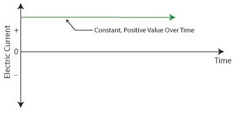
Figure 2 – The Workings of the Wall Wart Transformer What is depicted in the graph above is the oscilloscope’s ability to receive an electronic signal, measure it, graph it, and then display it on a screen. This enables us to see how the signal changes over time. At Point A, which represents the wall wart plugged into a wall outlet, the voltage alternates between positive 120 volts and negative 120 volts upon entering the wall wart, which will now act as a transformer. The wall wart transformer then does as its name suggests, it transforms the 120 volts coming from the outlet into the 12 volts shown at Point B. You will note that this lower voltage also alternates between positive and negative values, just as the original 120 volts emanating from the wall outlet did. In one of my earlier blogs I explained that transformers only work when the electricity passing through them alternates over time. (Click here for a refresher: Transformers ) High voltage alternating electricity in one transformer coil creates magnetic fields that induce alternating electricity at a different voltage in a second transformer coil. So when you put alternating voltage into the transformer, you get alternating voltage out. But that’s not the end of the story. Many electronic devices operate on voltage that doesn’t alternate. What then? Will our handy wall wart still be able to bridge the electrical gap to fill our needs? Next time we’ll see how the diode bridge and capacitor come into play to deal with the alternating voltage from the transformer in a manner eerily similar to a microwave oven’s high voltage circuit. ____________________________________________ |
Posts Tagged ‘12 volts’
Inside The Wall Wart
Monday, September 5th, 2011

Ever Had a Wall Wart?
Sunday, August 28th, 2011|
You might have had warts on your skin. They’re formed by viruses making a new home. If you’ve ever had one, you probably didn’t like it and found it hard to get rid of. Walls often have warts, too, although you probably didn’t identify them as such. “Wall Wart” is engineering talk for the black plastic protrusions you often find attached to the exterior of a wall outlet in modern homes. If you call them anything at all, it’s most likely “AC power adapters.” A typical wall wart is shown in Figure 1.
Figure 1 – A Typical Wall Wart Wall warts provide a handy, portable and easy to use conversionary power source for small electronic devices, including lamps, small appliances, and various modern day electronics. If you’re like me, you have lots of them scattered on the walls of your home and office. Most people come to use them when a need arises, say you bought a scanner for your computer. Beyond that they’re usually not given much thought, but today we’re going to explore them a bit. Suppose you’re an engineer and you’ve been asked to design an electronic product for household use. The product only requires 12 volts of direct current (DC) to operate, but you know that the typical home is wired to supply 120 volts of alternating current (AC). What can be done to rectify the discrepancy? Well, there are two distinct choices. One of the choices is to design electronic circuitry capable of converting 120 volts AC into 12 volts DC, then place it inside the product. But is this the best choice? Not really. It takes time to design custom circuitry, and doing so will add substantially to the design time and final cost of the product. This is especially true if the circuitry is produced in small quantities. Besides, if the electronic product is small, there may not be enough room inside to accommodate this type of circuitry. The smarter choice would be to buy a wall wart from another company that specializes in manufacturing them. They’re produced in huge quantities, so the cost is low. They also come in standard voltages, like 12 volts DC. And because the wall wart is external to the product housing, space inside is no longer a concern. It couldn’t be any easier or cost effective. Just plug the wall wart into your home electrical outlet, then plug in the product’s 12 volt DC cord. Done! Next time we’ll take a look at what’s going on inside your basic wall wart to see how it works. ____________________________________________
|


