Posts Tagged ‘design engineer’
Thursday, June 7th, 2018
|
Our last blog introduced a project I oversaw while acting as a design engineer in a food manufacturing plant. The objective was to deposit fruit jelly into raw pastry dough as it whizzed along a production line conveyor belt before being sent off for baking. A special piece of equipment known as a depositor would be required to meet this challenge, and we’ll take a look at how one functions today. In fact, a jelly depositor acts very much as a human heart, as they’re both examples of positive displacement pumps.
A depositor is a device specifically made for the food industry. It consists of a hopper to hold the product to be deposited, in this case fruit jelly, which is discharged by the hopper into a rotating diverter valve and then on to a positive displacement piston pump. See below.
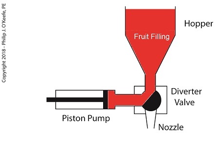
A Jelly Depositor is a Positive Displacement Pump
When the diverter valve rotates, a passageway opens to allow jelly to flow from the hopper into the piston pump. A pneumatic actuator, a device we’ll discuss in more depth next time, moves the pump’s piston to the left, away from the diverter valve, which allows the filling to be released into the pump from the hopper. At the end of the piston’s travel a set quantity of fruit jelly filling is drawn into the pump’s housing, just enough to fill one pastry. See below.
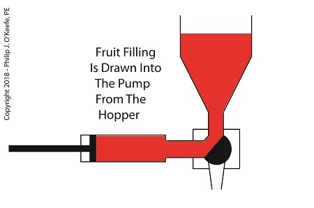
The Depositor Draws Filling Into The Pump
When the diverter valve rotates in the opposite direction, a passageway opens inside the valve that allows jelly filling to move from the pump to the nozzle. As the piston moves back toward the diverter valve the filling is forced out of the pump, through the nozzle, and into the pastry dough. The pump’s piston moves back and forth, that is, away from and then towards the transfer valve, ushering a set quantity of jelly filling through the mechanism each time. See below.
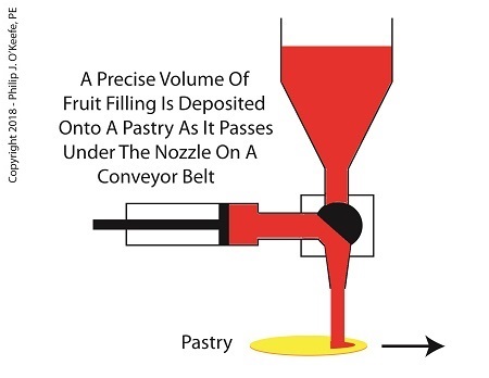
The Depositor Deposits The Filling
Now that we know how the depositor works, next time we’ll discuss the pneumatic actuator’s role in the filling process.
Copyright 2018 – Philip J. O’Keefe, PE
Engineering Expert Witness Blog
____________________________________ |
Tags: conveyor belt, depositor, design engineer, filling pastry, food industry, food manufacturing, food manufacturing plant, jelly depositor, piston pump, positive displacement pump
Posted in Engineering and Science, Expert Witness, Forensic Engineering, Innovation and Intellectual Property, Personal Injury, Product Liability | Comments Off on A Jelly Depositor is a Positive Displacement Pump
Monday, February 11th, 2013
| Last time we began our discussion on Preproduction, the final aspect of the Development stage of our systems engineering approach to medical device design. This is the point at which a small amount of devices are put into actual production, then evaluated for full production possibility. It is also the final juncture at which problems will be evaluated and corrected before full commercial production can begin.
Once the medical devices produced during Preproduction are assembled, they’re subjected to rigorous testing in both a laboratory and the field. This testing is necessary to see if stakeholder requirements are satisfied. At this stage devices constructed en masse on the factory assembly line are compared to prototypes built by hand by design engineers earlier in the Development stage.
During Preproduction laboratory test data is gathered and analyzed by engineers to assess how the device will hold up during actual use. Real-life conditions are simulated in the lab environment to facilitate this process. For example, lab testing of a Preproduction kidney dialysis machine can determine whether its blood pump flow rate falls within acceptable range during hundreds of hours of operation. Other factors, such as durability of materials are evaluated during lab testing. In the case of the dialysis machine, there is a component called a dialyzer that filters toxic waste from blood. Over the duration of the lab test, the material used in the dialyzer filter membranes would be inspected and evaluated for durability.
Next week we’ll conclude our discussion on Preproduction to see what happens when testing is moved outside the lab environment into the field.
___________________________________________

|
Tags: design engineer, design revision, Development Stage, durability of materials, engineering expert witness, factory assembly line, field testing, filter, filter membrane, flow rate, forensic engineer, lab testing, machine, maintenance instructions, manufacturing, medical device design, operating instructions, preproduction medical device, Production Stage, project stakeholder, pump, systems engineering in medical device design, test data, Utilization Stage
Posted in Engineering and Science, Expert Witness, Forensic Engineering, Innovation and Intellectual Property, Personal Injury, Product Liability | Comments Off on Systems Engineering In Medical Device Design – Preproduction, Part 2
Sunday, January 20th, 2013
| Last time we looked at the objective of the quality control department in the Production stage, that being to ensure that the end product produced fits all requirements. We learned that to meet this objective a great deal of collaboration must take place in the Development stage between quality control staff and design engineers in order to produce a complete set of instructions for quality control inspection and testing. Now let’s see how these instructions are developed.
Inspection and test methods are devised by the quality control department to ensure that a completed medical device lives up to its intended use. What good is a diagnostic imaging machine that doesn’t provide accurate internal views of a patient’s body? Or a heart defibrillator that sends electrical energy pulses to a patient’s heart muscles when it’s not supposed to? Quality control instructions are developed to guide inspection and testing methods so they’re performed correctly and consistently during the medical device Production stage. The objective is to catch problems before they occur.
For example, it can be specified that the plastic body components of a medical device be visually inspected after they are received from an outside vendor to check for undesirable defects, such as the presence of burrs, cracks, or non-uniform coloration. If anomalies are discovered, they’re documented, and the components are rejected. In other words, they are barred from being used in the assembly process.
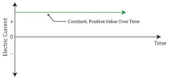
Quality testing methods are varied. They may involve hooking up the completed medical device to test instruments to simulate all possible modes of operation and any anticipated glitches that may occur during testing. While hooked up, the device’s operation is measured against key parameters to ensure that all is working well, and the data gathered is recorded and analyzed to see if operation is within normal limits. For example, an electric multimeter could be connected to the power cord of the device to measure how much electrical current is being drawn from the wall outlet during operation. If current drawn is too high, it may be indicative of a defective electrical component, and an in depth examination would follow.
Generally speaking, if test measurement parameters do not fall within acceptable limits as determined by previously established stakeholder requirements, then the medical device will be rejected by quality control. It will then be sent back to the manufacturing department, along with a detailed inspection and test report explaining why it was rejected. At this point the rejected device is either reworked or disposed of entirely.
Next time we’ll continue our discussion on the development of instructions for the Utilization stage, the stage where the medical device is actually put into use by the end user.
___________________________________________

|
Tags: design engineer, Development Stage, diagnostic imaging machine, disposal, electrical current, electrical energy pulses, engineering expert witness, forensic engineer, heart defibrillato, instructions, instrumentation, medical device design, Prouction Stage, quality control, quality control inspection and testing, quality control instructions, quality test methods, rejection, rework, stakeholder requirements, systems engineering, test measurement parameters, Utilization Stage
Posted in Engineering and Science, Expert Witness, Forensic Engineering, Innovation and Intellectual Property, Personal Injury, Product Liability | Comments Off on Systems Engineering In Medical Device Design – Instructions, Part 3
Sunday, November 6th, 2011
| Imagine going on a diet and not having a scale to check your progress, or going to the doctor and not having your temperature taken. Feedback is important in our daily lives, and industry benefits by it, too.
Generally speaking, feedback, or monitoring, is a tool that provides relevant information on a timely basis as to whether things are working as they were intended to. It’s an indispensable tool within the food manufacturing industry. Without it, entire plants could be erected exposing workers to injury and consumers to bacteria-laden products. It’s just plain common sense to monitor activities all along the way, starting with the design process. Now let’s see how monitoring is applied in HACCP Design Principle No. 4.
Principle 4: Establish critical control point monitoring requirements. – Monitoring activities are necessary to ensure that the critical limits established at each critical control point (CCP) established under Principle 3 discussed last week are working as intended. In other words, if the engineer identifies significant risks in the design of a piece of food processing equipment and establishes critical limits at CCPs to eliminate the risk, then the CCPs must be monitored to see if the risk has actually been eliminated.
Monitoring can and should be performed in food manufacturing plants by a variety of personnel, including design engineers, the manager of the engineering department, production line workers, maintenance workers, and quality control inspectors. For example, engineering department procedures in a food manufacturing plant should require the engineering manager to monitor CCPs established by the staff during the design of food processing equipment and production lines. Monitoring would include reviewing the design engineer’s plans, checking things like assumptions made concerning processes, calculations, material selections, and proposed physical dimensions.
In short, monitoring should be a part of nearly every process, starting with the review of design documents, mechanical and electrical drawings, validation test data for machine prototypes, and technical specifications for mechanical and electrical components. This monitoring would be conducted by the engineering manager during all phases of the design process and before the finished equipment is turned over to the production department to start production.
To illustrate, suppose the engineering manager is reviewing the logic in a programmable controller for a cooker on a production line. She discovers a problem with the lower critical limits established by her engineer at a CCP in the design of a cooker temperature control loop. You see, the time and temperature in the logic is sufficient to thoroughly cook smaller cuts of meat in most of the products that will be made on the line, however the larger cuts will be undercooked. The time and temperature settings within the logic are insufficient to account for the difference.
This situation illustrates the fact that monitoring does no good unless feedback is provided with immediacy. In our example, the design engineer who first established the CCP and the critical limits was not informed in a timely manner of the difference in cooking times that different size meats would require, resulting in the writing of erroneous software logic. Fortunately, continued monitoring by the engineering manager caught the error, leading her to provide feedback about it to the design engineer, who can then make the necessary corrections to the software.
Next week we’ll see what design engineers do with the feedback they’ve received, as seen through the eyes of HACCP Principle 5, covering the establishment of corrective actions.
____________________________________________

|
Tags: bacteria, bacteria-laden products, calculations, CCP, contamination, contoller, critical control point, critical limits, design documents, design engineer, engineering drawings, engineering expert witness, engineering manager, FDA, feedback, food equipment, food manufacturing, food plant, food processing equipment design, food production line, food safety, forensic engineer, HACCP, HACCP Principle 4, Hazard Analysis and Critical Control Point, injury, material selection, meat, monitoring, process control, programmable controller, risk elimination, temperature control, temperture, time, timer, validation testing
Posted in Engineering and Science, Expert Witness, Forensic Engineering, Innovation and Intellectual Property, Personal Injury, Product Liability | Comments Off on Food Manufacturing Challenges – HACCP Design Principle No. 4
Sunday, October 16th, 2011
| Imagine a doctor not washing his hands in between baby deliveries. Unbelievable but true, this was a widespread practice up until last century when infections, followed by death of newborns, was an all-too common occurrence in hospitals across the United States. It took an observant nurse to put two and two together after watching many physicians go from delivery room to delivery room, mother to mother, without washing their hands. Once hand washing in between deliveries was made mandatory, the incidence of infection and death in newborns plummeted.
Why wasn’t this simple and common sense solution instituted earlier? Was it ignorance, negligence, laziness, or a combination thereof that kept doctors from washing up? Whatever the root cause of this ridiculous oversight, it remains a fact of history. Common sense was finally employed, and babies’ lives saved.
The same common sense is at play in the development of the FDA’s Hazard Analysis Critical Control Point (HACCP) policy, which was developed to ensure the safe production of commercial food products. Like the observant nurse who played watchdog to doctors’ poor hygiene practices and became the catalyst for improved hospital procedures set in place and remaining until today, HACCP policy results in a proactive strategy where hazards are identified, assessed, and then control measures developed to prevent, reduce, and eliminate potential hazards.
In this article, we’ll begin to explore how engineers design food processing equipment and production lines in accordance with the seven HACCP principles. You will note that here, once again, the execution of common sense can solve many problems.
Principle 1: Conduct a hazard analysis. – Those involved in designing food processing equipment and production lines must proactively analyze designs to identify potential food safety hazards. If the hazard analysis reveals contaminants are likely to find their way into food products, then preventive measures are put in place in the form of design revisions.
For example, suppose a food processing machine is designed and hazard analysis reveals that food can accumulate in areas where cleaning is difficult or impossible. This accumulation will rot with time, and the bacteria-laden glop can fall onto uncontaminated food passing through production lines.
As another example, a piece of metal tooling may have been designed with the intent to form food products into a certain shape, but hazard analysis reveals that the tooling is too fragile and cannot withstand the repeated forces imposed on it by the mass production process. There is a strong likelihood that small metal parts can break off and enter the food on the line.
Next time we’ll move on to HACCP Principle 2 and see how design engineers control problems identified during the hazard analysis performed pursuant to Principle 1.
____________________________________________

|
Tags: bacteria, cleaning, commercial food products, contaminant in food, conveyor belt, design engineer, engineering expert witness, FDA, food contamination, food manufacturing, food processing equipment design, food production line, forensic engineer, HACCP, HACCP Principle 1, hazard analysis, hazard analysis critical control point, risk analysis, tooling
Posted in Engineering and Science, Forensic Engineering, Personal Injury, Product Liability | Comments Off on Food Manufacturing Challenges – HACCP Design Principle No. 1
Sunday, October 9th, 2011
| Perhaps you’ve heard of the non-reciprocal wine and sewage principle. I’m not sure where it originated, but it states that if you add a cup of wine to a barrel of sewage, you still get a barrel of sewage. No brainer, right? Well, consider the flip side. If you add a cup of sewage to a barrel of wine, you also get nothing more than a barrel of sewage. In other words, a small amount of contamination goes a long way.
The premise of this principle also applies within the food manufacturing industry. If you were to add uncontaminated food to garbage, you would just get more garbage, and if you add garbage to food… well, you get it. The term garbage can encompass an endless variety of contaminants, such as broken glass, metal shavings, nuts, bolts, plastic fibers, grease, broken machine parts, errant human body parts, and on and on. Although the FDA does allow for certain levels of natural contaminants, like insect parts and rodent hairs, consumers are never pleased when undesirable elements enter their food supply. It could even be dangerous.
When design engineers create food processing machinery and production lines, they must be on the lookout for potential risks of contamination hazards. They must also provide a quick means of mitigation, before contaminants can enter into commercial production. A systematic approach provides the best means of addressing these needs, allowing for a pre-emptive method to ensure food safety. Checklists and procedural policy set in place for these reasons will enable design engineers to identify, assess, and control risks before they turn into hazards. This is where Hazard Analysis Critical Control Point (HACCP) planning comes in.
To address these needs, the FDA has set up the HACCP (pronounced, “hass-up”) system, defined as “…a management system in which food safety is addressed through the analysis and control of biological, chemical, and physical hazards from raw material production, procurement and handling, to manufacturing, distribution and consumption of the finished product.”
HACCP is the outgrowth of FDA current Good Manufacturing Practices (cGMP), which are set out in the Code of Federal Regulations pertaining to commercial food processors and manufacturers, Title 21, Part 110, entitled, “current Good Manufacturing Practice in Manufacturing, Packing or Holding Human Food.” Every commercial food processor, regardless of size, must implement a cGMP/HACCP quality assurance program to comply with these regulations.
HACCP is a proactive strategy where hazards are identified, assessed, and then control measures developed to prevent, reduce, or eliminate potential hazards. A key element of HACCP involves prevention of food contamination during all phases of manufacturing, and way before the finished food product undergoes quality inspection. This strategy extends into the food manufacturing equipment and production line design process as well.
Next time we’ll continue our look at HACCP and how its seven principles are used by design engineers to prevent food product contamination.
____________________________________________

|
Tags: cGMP, current good manufacturing practices, design engineer, engineering expert witness, FDA, food contamination hazard, food processing machinery, food product contamination, food production line, forensic engineer, HACCP, hazard analysis critical control point, quality assurance program, quality inspection, risk analysis
Posted in Engineering and Science, Expert Witness, Forensic Engineering, Personal Injury, Product Liability, Professional Malpractice | Comments Off on Food Manufacturing Challenges – Avoiding Contamination
Monday, October 3rd, 2011
| My wife and I have an agreement concerning the kitchen. She cooks, I clean. Plates and utensils are easy enough to deal with, especially when you have a dishwasher. Pots and pans are a little more challenging. But what I hate the most are the food processors, mixers, blenders, slicers and dicers. They’re designed to make food preparation easier and less time consuming, but they sure don’t make the clean up any easier! Quite frankly, I suspect the time involved to clean them exceeds the time saved in food preparation.
Food processors on a larger scale are also used to manufacture many food products in manufacturing facilities, and being larger and more complicated overall, they’re even more difficult to clean. For example, I once designed a production line incorporating a dough mixer for one of the largest wholesale bakery product suppliers in the United States. A small elevator was required to lift vast amounts of ingredients into a mixing bowl the size of a compact car. Its mixing arms were so heavy, two people were required to lift them into position. It was also my task to ensure that the equipment as designed was capable of being thoroughly cleaned in a timely and cost effective manner.
Food processing machinery must be designed so that all areas coming into contact with ingredients can be readily accessed for cleaning. And since most of the equipment you are dealing with in this setting is far too cumbersome to be portable, the majority of the cleaning must be cleaned in place, known in the industry as CIP. To facilitate CIP, commercial machinery is designed with hatches and special covers that allow workers to get inside with their cleaning equipment. Small, portable parts of the machine, such as pipes, cutting blades, forming mechanisms, and extrusion dies, are often made to be removable so that they can be carried over to an industrial sized sink for cleaning out of place, or COP. These potable machine components are typically removable for COP without the use of any tools and are fitted with flip latches, spring clips, and thumb screws to facilitate the process.
Everything in a food manufacturing facility, from production machinery to conveyor belts, is typically cleaned with hot, pressurized water. The water is ejected from the nozzle end of a hose hooked up to a specially designed valve that mixes steam and cold water. The result is scalding hot pressurized water that easily dislodges food residues. Bacteria doesn’t stand a chance against this barrage. The water, which is maintained at about 180°F, quickly sterilizes everything it makes contact with. It also provides a chemical-free clean that won’t leave behind residues. Once dislodged, debris is flushed out through strategically placed openings in the machine which then empty into nearby floor drains.
As a consequence of the frequent cleanings commercial food preparation machinery requires, their parts must be able to withstand frequent exposure to high pressure water streams. Parts are typically constructed of ultra high molecular weight (UHMW) food-grade plastics and metal alloys such as stainless steels, capable of withstanding the corrosive effects of water. And since water and electricity make a dangerous combination, gaskets and seals on the equipment must be tight enough to protect against water making its way into motors and other electrical parts.
Next time we’ll look at how design engineers of food manufacturing equipment use a systematic approach to minimize the possibility of food safety hazards, such as product contamination.
____________________________________________

|
Tags: bacteria, bakery product, blender, CIP, clean in place, clean out of place, cleanliness, commercial machinery, conveyor belt, COP, corrosion, cover, design engineer, dough, drain, electrical part, electricity, elevator, engineering expert witness, extrusion die, food manufacturer, food manufacturing, food processing equipment, food processing machinery, food processor, food production line, forensic engineer, forming mechanism, gasket, hatch, high pressure hot water, latch, mixer, mixing arm, mixing bowl, mixing valve, nozzle, product contamination, safety hazard, sanitary piping, seal, spring clip, stainless steel, steam, sterilization, thumb screw, UHMW, ultra high molecular weight plastic
Posted in Engineering and Science | Comments Off on Food Manufacturing Challenges – Cleanliness
Sunday, August 28th, 2011
|
You might have had warts on your skin. They’re formed by viruses making a new home. If you’ve ever had one, you probably didn’t like it and found it hard to get rid of.
Walls often have warts, too, although you probably didn’t identify them as such. “Wall Wart” is engineering talk for the black plastic protrusions you often find attached to the exterior of a wall outlet in modern homes. If you call them anything at all, it’s most likely “AC power adapters.” A typical wall wart is shown in Figure 1.

Figure 1 – A Typical Wall Wart
Wall warts provide a handy, portable and easy to use conversionary power source for small electronic devices, including lamps, small appliances, and various modern day electronics. If you’re like me, you have lots of them scattered on the walls of your home and office. Most people come to use them when a need arises, say you bought a scanner for your computer. Beyond that they’re usually not given much thought, but today we’re going to explore them a bit.
Suppose you’re an engineer and you’ve been asked to design an electronic product for household use. The product only requires 12 volts of direct current (DC) to operate, but you know that the typical home is wired to supply 120 volts of alternating current (AC). What can be done to rectify the discrepancy? Well, there are two distinct choices.
One of the choices is to design electronic circuitry capable of converting 120 volts AC into 12 volts DC, then place it inside the product. But is this the best choice? Not really. It takes time to design custom circuitry, and doing so will add substantially to the design time and final cost of the product. This is especially true if the circuitry is produced in small quantities. Besides, if the electronic product is small, there may not be enough room inside to accommodate this type of circuitry.
The smarter choice would be to buy a wall wart from another company that specializes in manufacturing them. They’re produced in huge quantities, so the cost is low. They also come in standard voltages, like 12 volts DC. And because the wall wart is external to the product housing, space inside is no longer a concern. It couldn’t be any easier or cost effective. Just plug the wall wart into your home electrical outlet, then plug in the product’s 12 volt DC cord. Done!
Next time we’ll take a look at what’s going on inside your basic wall wart to see how it works.
____________________________________________

|
Tags: 12 volts, 120 volts, AC, AC power adapter, alternating current, DC, design engineer, direct current, electronic device, electronic product, engineering expert witness, forensic engineer, power cord, power supply, wall outlet, wall wart
Posted in Engineering and Science, Expert Witness, Forensic Engineering, Personal Injury, Product Liability | Comments Off on Ever Had a Wall Wart?


