Archive for November, 2012

Systems Engineering In Medical Device Design – Introduction

Monday, November 26th, 2012
     I once worked with a medical device design engineer who, although talented enough, was not adept in the subtle yet indispensable skill of verbal communication.  He lacked a concise, organized approach to his projects, and his problem solving skills were unilateral and obtuse, that is to say, his only aim was to satisfy his personal requirements, what he felt was important.  Creative problem solving and brainstorming with customers as to what they desired did not fall within his repertoire.  As a result customer complaints and a long string of product failures eventually led to him losing his position.

     Where specifically had he failed?  The net result of his approach was that he designed devices that did not deliver the desired customer results.  They also had a varying tendency to be either unnecessarily expensive to produce, unreliable to operate, or difficult to service.  All concerned with the product were often dissatisfied, from customers to service technicians.  This caused the company we worked for to incur considerable expense to rectify his design errors.  The company also lost some of their customer base to competitors.  Sadly, none of this would have happened if my coworker had used a systems engineering approach in designing his projects.

     Before we get any further into a discussion on systems engineering, let’s get a handle on what is meant by a system.  In a nutshell, a system is a combination of interacting components that are organized to achieve one or more specific purposes.  The components can be tools, machine parts, electronics, people, or any combination thereof.  For example, hundreds of parts can be combined by a manufacturer into a system to form a medical device such as an x-ray film developing machine, the end result of which is to produce a film of diagnostic quality. 

      The system part of Systems Engineering stays true to this definition. It is an interdisciplinary approach to complex engineering projects which guides all activities during the course of a product’s life cycle, from conception to production. While doing so it will integrate and monitor work processes between all departments involved, with a constant eye towards optimization of processes and reduction of costs in order to satisfy stakeholder requirements.

     A key objective of systems engineering is to produce systems that satisfy stakeholder needs by producing reliable, cost effective, and safe products capable of performing tasks as designated by the customer.  Within the medical device arena stakeholders include patients, nurses, doctors, the US Food and Drug Administration (FDA), device service technicians, device dealers, as well as the device manufacturer.

     Next time we’ll begin our exploration of how systems engineering addresses the medical device design process with a discussion on the first of its five stages, known as Concept.

____________________________________________

 Systems Engineering In Medical Device Design

Transistors – Voltage Regulation, Final Chapter

Monday, November 19th, 2012

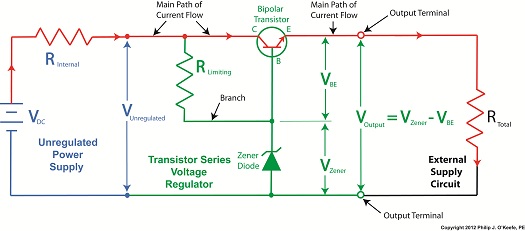
     Last time we learned how the transistor opens a path for electric current to flow from the collector to the emitter in our example circuit.  It does so by making use of an unregulated power supply.  Now let’s see how the Zener diode fits into the mix.

transistor series voltage regulator

Figure 1


     It just so happens that bipolar transistors, like the one in our example circuit in Figure 1, are designed so that voltage at its emitter is dependent upon the voltage applied at its base.  This makes them ideal for use in voltage regulator circuits where this kind of predictability is required.

     For example, in our transistor series voltage regulator, the Zener diode is connected to the transistor’s base, B.  When the branch current flows from RLimiting down through the diode, a Zener voltage, VZener, is established.  Since the diode is connected to the transistor, VZener voltage is also applied to the transistor’s base.  Thus the transistor’s emitter voltage will be regulated according to the Zener voltage.

     Bipolar transistors are designed by manufacturers to typically operate with a standardized voltage difference of 0.6 volts between the base and emitter.  This is represented in Figure 1 as VBE, where BE stands for base-emitter.  VBE is standardized at a known quantity of 0.6 volts to simplify things within the industry and aid engineers in their calculations to design transistor circuits, as we’ll now see.

     With the Zener diode connected to the transistor base in our example circuit, the voltage difference is denoted as:

VBE = VZener   VE

where VE is the emitter voltage.  Rearranging terms to solve for VE, we get:

VE = VZener – VBE

Inserting VBE,  which we know is standardized at 0.6 volts:

VE = VZener – 0.6 volts

Since the emitter is physically connected to the output terminal of the transistor series voltage regulator, the emitter voltage is going to be equal to the output voltage, VOut.

     We learned earlier in this series of articles that VZener is a reliable source of consistent voltage.  Because it is present in our transistor series voltage regulator, our example circuit will produce a nice, constant regulated output voltage of VZener – 0.6 volts, a voltage that is useful for many of today’s applications.  However the transistor series voltage regulator provides us with a major advantage over the Zener diode voltage regulator circuit.

     The advantage of a transistor series voltage regulator lies in the fact that  RLimiting is on a separate branch all to its own within the regulator circuit, and because of this it no longer acts as a roadblock to limit the main path of current flow, as happens within the Zener diode voltage regulator circuit discussed previously.  Refer to the red path shown in Figure 1.  With RLimiting in this position the transistor series voltage regulator is able to feed more current to the external supply circuit than is possible through the Zener diode voltage regulator alone.  This means it can be used in more power hungry applications like energizing today’s TVs and modern kitchen appliances.

     That wraps up our discussion on transistors.  Next time we’ll begin a new topic, how medical devices can be designed using systems engineering, a systematic approach that ensures that designed devices satisfy both user and regulatory requirements.

____________________________________________


Transistors – Voltage Regulation Part XVII

Monday, November 12th, 2012

     Last time we learned about a new type of transistor called a bipolar transistor and how it controls the flow of electric current traveling from the collector to the emitter within our circuit.  We also saw how the bipolar transistor is integrated within a Zener diode voltage regulator circuit to make a new type of circuit called a transistor series voltage regulator.

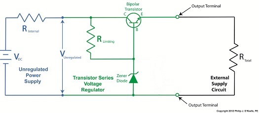
     Now let’s see how this all works by hooking our circuit up to both an unregulated power supply and an external supply circuit as shown in Figure 1.

transistor voltage regulator circuit

Figure 1


     When voltage VUnregulated is applied to our transistor series voltage regulator circuit by way of an unregulated power supply, electric current flows through RLimiting into the base, B, of the transistor.  The transistor senses this current and responds by opening a path for current to flow from its collector, C, to its emitter, E.  With this path established, current flows freely from the unregulated power supply, through the transistor’s collector and emitter, on to the output terminal, and finally to the external supply circuit.  Total resistance of this circuit is said to be RTotal

     At this point you’re probably wondering why the bipolar transistor base and Zener diode are connected to RLimiting.  Next time we’ll conclude our series by seeing how this connection is crucial to the functionality of our transistor series voltage regulator.

____________________________________________ 


Transistors – Voltage Regulation Part XVI

Monday, November 5th, 2012

     We’ve been discussing the Zener diode voltage regulator circuit, its advantages and disadvantages.  We learned that the limiting resistor, RLimiting, creates a major disadvantage in the operation of the circuit, effectively acting as a roadblock to restrict current flow.  Let’s see how to improve on that. 

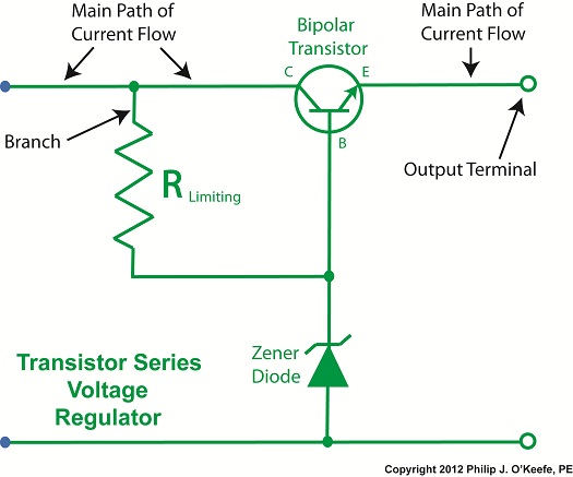
     Figure 1 illustrates a transistor series voltage regulator circuit.


transistor series voltage regulator with Zener diode

Figure 1


     In this circuit the transistor is known as a bipolar transistor.   Like the FET we discussed earlier, it has three electrical connections, however on the bipolar transistor the connections are referred to as the collector, base, and emitter.  These are labeled C, B, and E in Figure 1.

     The bipolar transistor acts as a valve, resting within the main path of current flow.  That is, it controls the flow of electric current traveling from the collector to the emitter, as well as the voltage available at the emitter.  The transistor is designed so that current flows in one direction only, from collector to emitter.  We’ll talk more about that in our next article.

     The limiting resistor, RLimiting, is located on a branch of the circuit leading to the Zener diode and the transistor base.  Next time we’ll connect an unregulated power supply and external supply circuit to our transistor series voltage regulator.  This will enable us to see how placing RLimiting on the branch, rather than along the main current path, results in a major advantage over using the Zener diode voltage regulator alone.  

____________________________________________