Posts Tagged ‘Zener Voltage’

Transistors – Voltage Regulation, Final Chapter

Monday, November 19th, 2012

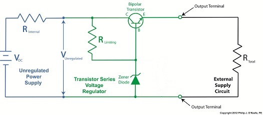
     Last time we learned how the transistor opens a path for electric current to flow from the collector to the emitter in our example circuit.  It does so by making use of an unregulated power supply.  Now let’s see how the Zener diode fits into the mix.

transistor series voltage regulator

Figure 1


     It just so happens that bipolar transistors, like the one in our example circuit in Figure 1, are designed so that voltage at its emitter is dependent upon the voltage applied at its base.  This makes them ideal for use in voltage regulator circuits where this kind of predictability is required.

     For example, in our transistor series voltage regulator, the Zener diode is connected to the transistor’s base, B.  When the branch current flows from RLimiting down through the diode, a Zener voltage, VZener, is established.  Since the diode is connected to the transistor, VZener voltage is also applied to the transistor’s base.  Thus the transistor’s emitter voltage will be regulated according to the Zener voltage.

     Bipolar transistors are designed by manufacturers to typically operate with a standardized voltage difference of 0.6 volts between the base and emitter.  This is represented in Figure 1 as VBE, where BE stands for base-emitter.  VBE is standardized at a known quantity of 0.6 volts to simplify things within the industry and aid engineers in their calculations to design transistor circuits, as we’ll now see.

     With the Zener diode connected to the transistor base in our example circuit, the voltage difference is denoted as:

VBE = VZener   VE

where VE is the emitter voltage.  Rearranging terms to solve for VE, we get:

VE = VZener – VBE

Inserting VBE,  which we know is standardized at 0.6 volts:

VE = VZener – 0.6 volts

Since the emitter is physically connected to the output terminal of the transistor series voltage regulator, the emitter voltage is going to be equal to the output voltage, VOut.

     We learned earlier in this series of articles that VZener is a reliable source of consistent voltage.  Because it is present in our transistor series voltage regulator, our example circuit will produce a nice, constant regulated output voltage of VZener – 0.6 volts, a voltage that is useful for many of today’s applications.  However the transistor series voltage regulator provides us with a major advantage over the Zener diode voltage regulator circuit.

     The advantage of a transistor series voltage regulator lies in the fact that  RLimiting is on a separate branch all to its own within the regulator circuit, and because of this it no longer acts as a roadblock to limit the main path of current flow, as happens within the Zener diode voltage regulator circuit discussed previously.  Refer to the red path shown in Figure 1.  With RLimiting in this position the transistor series voltage regulator is able to feed more current to the external supply circuit than is possible through the Zener diode voltage regulator alone.  This means it can be used in more power hungry applications like energizing today’s TVs and modern kitchen appliances.

     That wraps up our discussion on transistors.  Next time we’ll begin a new topic, how medical devices can be designed using systems engineering, a systematic approach that ensures that designed devices satisfy both user and regulatory requirements.

____________________________________________


Transistors – Voltage Regulation Part X

Monday, September 24th, 2012
     Through the ages it’s been common practice to name important discoveries after those who discovered them.  For example, James Watt was a mechanical engineer who improved the steam engine by finding a solution to the problem of steam condensing into water inside the engine, a phenomenon which resulted in the engine cooling and reducing its efficiency.  Thus it was fitting that a metric unit of power, the watt, was named in his honor.  Today we’ll become acquainted with the man behind the naming of the Zener diode, Clarence Zener, and take a look at his contributions with regard to the function of this electrical component.

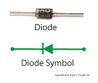
     Last time we began our discussion on electrical components known as diodes and saw how they’re used on circuit paths to govern the flow of current.  The Zener diode is a particular type of diode and a key component in transistorized voltage regulator circuits, as we’ll see later.  For now, let’s see how it works.     The symbol for the Zener diode is almost identical to that of a standard diode, introduced in my previous blog, but the Zener version has a bent line going through it resembling a distorted letter “z.”  See Figure 1.

Zener diode voltage regulator

Figure 1       


      Electric current flows through the Zener Diode just as it does through a standard diode.  But when the current flows in reverse, that’s where the similarity ends.  See Figure 2.

  Zener diode

Figure 2    


     When current tries to flow in the reverse direction, the Zener diode acts as an electrical conductor and allows current to pass through it.  In other words, it doesn’t block current flow as standard diodes do.

      At this point, you may be asking, “What’s so special about that?”  Perhaps you’ve made the connection that it behaves no differently than a metal wire.  But that isn’t entirely correct.

     You see, when current passes in the reverse direction through the Zener diode, it maintains a constant voltage.  This is called the Zener Voltage and is denoted as VZener.  The significance here is that within the circuit, any electronic component connected across the leads of a Zener diode will be supplied with a constant, unchanging voltage.  Thus the Zener diode works as a voltage regulator, enabling devices connected to it to have smooth, uninterrupted operation at a constant voltage.  It should be noted that this phenomenon only happens when the current flowing through the Zener diode is flowing in reverse.

     Next time we’ll look at a basic regulated power supply circuit to see how a Zener diode is incorporated in order to maintain a consistent output voltage.

____________________________________________