| Through the ages it’s been common practice to name important discoveries after those who discovered them. For example, James Watt was a mechanical engineer who improved the steam engine by finding a solution to the problem of steam condensing into water inside the engine, a phenomenon which resulted in the engine cooling and reducing its efficiency. Thus it was fitting that a metric unit of power, the watt, was named in his honor. Today we’ll become acquainted with the man behind the naming of the Zener diode, Clarence Zener, and take a look at his contributions with regard to the function of this electrical component.
Last time we began our discussion on electrical components known as diodes and saw how they’re used on circuit paths to govern the flow of current. The Zener diode is a particular type of diode and a key component in transistorized voltage regulator circuits, as we’ll see later. For now, let’s see how it works. The symbol for the Zener diode is almost identical to that of a standard diode, introduced in my previous blog, but the Zener version has a bent line going through it resembling a distorted letter “z.” See Figure 1.
Figure 1
Electric current flows through the Zener Diode just as it does through a standard diode. But when the current flows in reverse, that’s where the similarity ends. See Figure 2. Figure 2
When current tries to flow in the reverse direction, the Zener diode acts as an electrical conductor and allows current to pass through it. In other words, it doesn’t block current flow as standard diodes do. At this point, you may be asking, “What’s so special about that?” Perhaps you’ve made the connection that it behaves no differently than a metal wire. But that isn’t entirely correct. You see, when current passes in the reverse direction through the Zener diode, it maintains a constant voltage. This is called the Zener Voltage and is denoted as VZener. The significance here is that within the circuit, any electronic component connected across the leads of a Zener diode will be supplied with a constant, unchanging voltage. Thus the Zener diode works as a voltage regulator, enabling devices connected to it to have smooth, uninterrupted operation at a constant voltage. It should be noted that this phenomenon only happens when the current flowing through the Zener diode is flowing in reverse. Next time we’ll look at a basic regulated power supply circuit to see how a Zener diode is incorporated in order to maintain a consistent output voltage. ____________________________________________ |
Posts Tagged ‘transistorized voltage regulator circuits’
Transistors – Voltage Regulation Part X
Monday, September 24th, 2012

Transistors – Voltage Regulation Part IX
Sunday, September 16th, 2012| One way streets frustrate me, and I usually end up wasting a lot of time and gas driving in circles to get to my destination. Generally speaking, I prefer a two way street. Electric current flowing through electronic circuits is somewhat analogous to traffic flow. There are circuit paths that act like one way streets and others that act like two-way.
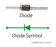
An electrical component called a diode can be used on circuit paths to govern the flow of current. They are a key component in basic transistorized voltage regulator circuits, as we’ll see later. For now, let’s get a basic understanding of how they work. Diodes are typically made of a semiconductor material, such as the element germanium. These materials behave in a complex way that fall along the lines of quantum physics. Esoteric phrases such as electron-hole theory, crystalline atomic lattice theory, and impurity doping are some of the concepts involved and would require a book onto themselves to explain. For the purposes of this article all we have to know is that semiconductors have two properties. The first property is that of an electrical conductor, that is, a material which allows electric current to pass through it. Copper wire is a good example of this. The second property is that of an electrical insulator, which blocks the flow of electric current. Materials such as glass, wood, and rubber fall into the insulator category. A photo of a diode is shown in Figure 1, along with its symbol used in electrical schematics.
Figure 1
When electric current flows through a diode in one direction, as shown in Figure 2, the semiconductor material inside of it acts as a conductor, ushering it along a single path.
Figure 2
When current tries to flow through the diode in the reverse direction, the semiconductor material acts as an insulator. That is, it blocks the flow of current as shown in Figure 3.
Figure 3
So we see that diodes can act like one way streets, restricting current flow. But, not all diodes work this way. Next week we’ll introduce a special kind of diode called the Zener diode, which allows current to flow in two different directions, and we’ll see how this functionality is put to work in regulated power supplies. ____________________________________________ |


